Impact crusher blow bars operate under repeated high-energy impact and abrasive contact as the rotor accelerates incoming rock through the crushing chamber. Their working surfaces gradually lose material, while changes in wear depth, profile, and surface condition can reveal problems with feed distribution, rotor operation, material selection, or component installation.
A blow bar that performs well in limestone crushing may wear prematurely when processing highly abrasive granite or reinforced concrete. Understanding the dominant wear mechanism is essential when selecting replacement impact crusher blow bars, evaluating component quality, and controlling operating costs.
How Blow Bars Wear During Impact Crushing
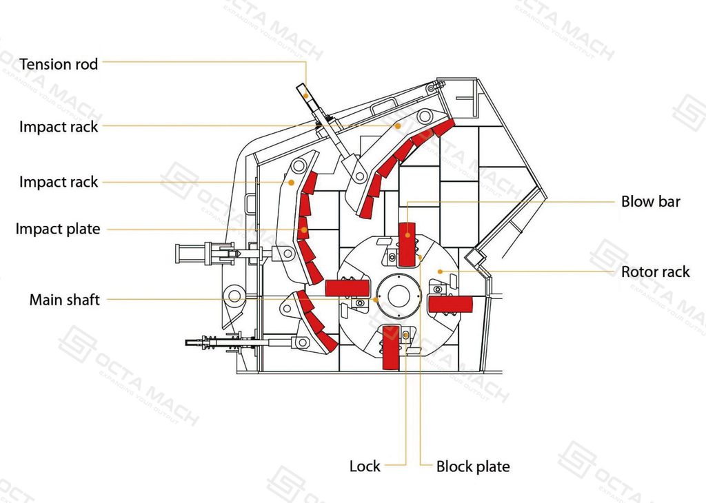
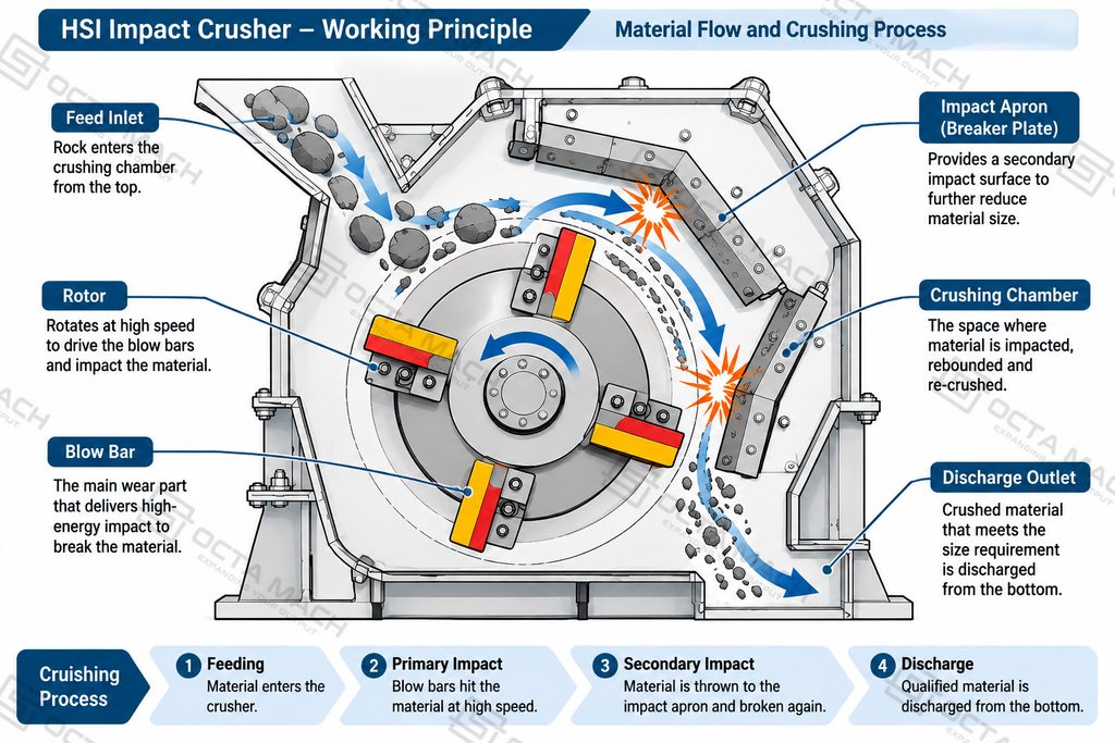
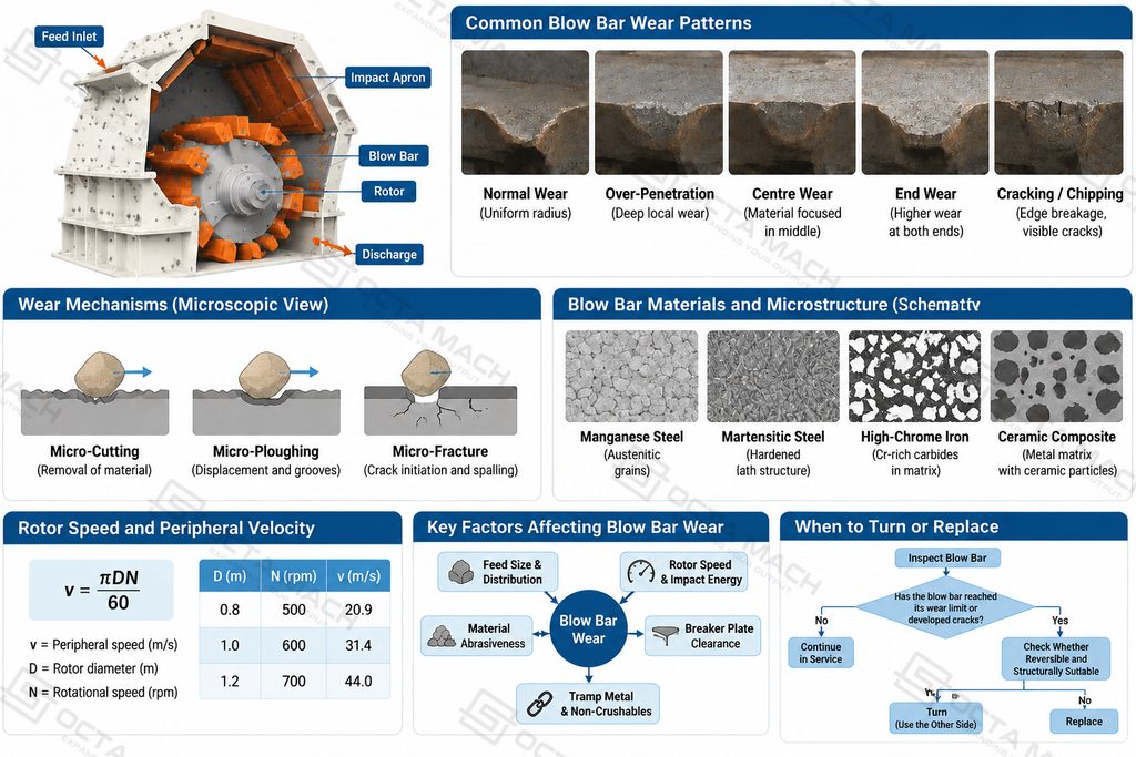
Blow bars are installed around the rotor of a horizontal shaft impact (HSI) crusher. As the rotor rotates, the bars strike incoming material and accelerate it toward the impact aprons or breaker plates. The rock undergoes repeated impact, fracture, and size reduction before moving toward the discharge area.
The working edge and face experience two main forms of material loss: abrasive wear and impact-related damage. These mechanisms often occur simultaneously, but their relative importance changes with feed size, mineral composition, rotor speed, and the presence of uncrushable objects.
Abrasive Wear on the Working Surface
Abrasive wear develops when hard mineral particles slide, roll, or become trapped between the blow bar and the material being processed. Quartz-bearing rock is particularly important because hard mineral grains can progressively remove material from the exposed steel surface.
At the microscopic level, abrasive wear can occur through several mechanisms:
- Micro-cutting: Hard particles penetrate the metal surface and remove small fragments as they move across it.
- Micro-ploughing: Abrasive particles displace metal sideways, forming grooves and raised ridges without immediately removing all displaced material.
- Micro-fracture: Brittle phases, particularly carbide-rich regions, may develop microcracks or detach when local contact stresses exceed their resistance. This can accelerate material loss under repeated abrasive loading.
These mechanisms gradually reduce the working thickness and change the geometry of the blow bar. As the leading edge becomes rounded or recessed, the contact relationship between the bar and incoming rock also changes, potentially affecting impact efficiency and the usable wear section.
Impact-Related Cracking and Fracture
Repeated impact loading can cause local plastic deformation and stress concentrations, particularly around sharp edges, geometric transitions, and casting discontinuities.The most exposed areas are often the leading edge, corners, and transitions between the working face and the supporting body.
Repeated impact can initiate small surface cracks, particularly around casting defects, sharp geometric transitions, or regions with inadequate toughness. Once a crack forms, subsequent loading may extend it through the material until a piece of the working edge breaks away.
The distinction between abrasion and impact fatigue is important. A bar that gradually loses material through uniform abrasion may remain serviceable, while a bar with relatively little overall wear can still require immediate replacement if a structural crack develops.
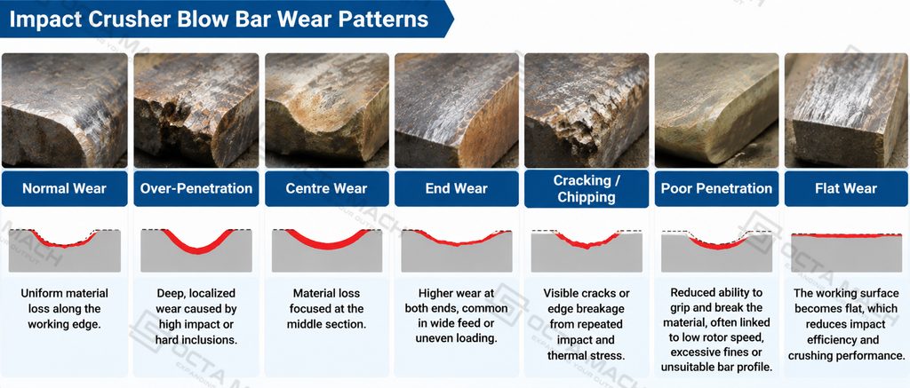
Common Blow Bar Wear Patterns
The distribution of material loss across a blow bar provides useful evidence about the crushing process. Inspection should cover the complete working face, both ends, the leading edge, and the remaining body thickness rather than focusing only on the deepest worn area.
1. Normal and Uniform Wear
Normal wear generally produces a gradual radius along the working edge, with material loss distributed relatively evenly across the active width. The working profile becomes progressively rounded rather than developing a deep local groove or sharp notch.
This pattern is generally associated with stable feed distribution, suitable rotor operation, and an appropriate material grade. The available wear section is used more consistently, reducing the likelihood of premature replacement caused by localized damage.
A gradual wear profile does not necessarily mean that the bar has reached its full usable life. Remaining thickness, mounting condition, and the manufacturer’s permitted wear limit must still be checked.
2. Over-Penetration and Deep Local Wear
Over-penetration occurs when wear develops too deeply into a particular section of the blow bar. Instead of forming a gradual working radius, the bar develops a pronounced recessed area or deep wear groove.
Low rotor speed can contribute to this condition in certain crusher configurations because it changes how the bar engages and penetrates incoming material. Feed size, bar geometry, and rotor configuration should also be examined before changing the operating speed.
Deep localized wear is important because it can leave substantial unused material elsewhere on the bar. It may also reduce the remaining cross-section available to withstand impact loading, increasing the risk of breakage.
3. Centre and End Wear
Centre wear and end wear are often associated with uneven feed distribution across the rotor width. When material consistently enters one region of the crushing chamber, the corresponding blow bar sections experience a different loading pattern from the rest of the working surface.
| Wear Pattern | Possible Cause | Inspection Priority |
|---|---|---|
| Heavy centre wear | Concentrated feed or uneven loading | Feed chute alignment and material distribution |
| Both-end wear | Feed concentrated toward the rotor edges | Feed width and chute configuration |
| One-end wear | Off-centre feeding or uneven material flow | Feed direction and chute position |
| Irregular localized wear | Variable feed conditions or inconsistent engagement | Feed gradation and rotor configuration |
These patterns are diagnostic indicators, not definitive proof of a particular fault. The actual feed trajectory and wear distribution should be checked together before changing the blow bar alloy or rotor settings.
4. Poor Penetration and Flat Wear
Poor penetration occurs when the blow bar does not engage incoming material effectively, reducing the impact transferred to the feed. Excessive fines, unsuitable rotor speed, or an unfavorable feed trajectory may contribute to this condition.
Flat wear describes a relatively broad, flattened working surface that develops as the original blow bar profile is gradually lost. Feed gradation, rotor speed, and breaker plate clearance should be checked together to identify the cause.
5. Chipping and Cracking
Chipping occurs when small sections of the leading edge or working surface break away. Cracking may extend deeper into the bar and eventually cause a larger section to detach.
Common contributing conditions include oversized feed, tramp metal, excessive impact loading, insufficient material toughness, and damaged or improperly secured retaining components.
The microscopic failure mechanism can involve crack initiation at local stress concentrations, followed by crack propagation under repeated loading. In cast components, inclusions, porosity, and other discontinuities may also act as potential crack initiation sites.
A cracked or broken bar should not be treated as normal wear. The rotor, seating surfaces, locking wedges, and other installed bars should be inspected before the crusher returns to operation.
Factors That Accelerate Blow Bar Wear
The service life of impact crusher blow bars depends on the interaction between feed characteristics, operating conditions, and material properties. Premature wear should therefore be investigated systematically rather than automatically attributed to poor alloy quality.
Feed Size and Distribution
Oversized particles increase the impact load on the working edge, especially when large blocks enter the crushing chamber at irregular intervals. This can produce local deformation, edge chipping, or cracking.
Feed distribution is equally important. Material entering predominantly on one side of the rotor creates uneven contact across the bar width. Consistent feeding helps distribute loading and makes better use of the available wear material.
The maximum feed size must remain within the limits specified for the crusher model. The nominal feed opening alone should not be used to establish an allowable maximum rock size.
Rotor Speed and Impact Energy
Rotor peripheral speed influences the velocity at which blow bars contact incoming material and therefore affects the impact conditions inside the crushing chamber. For a rotor with a given effective radius, its peripheral speed is:
v = πDN 60
Where:
- v = Rotor peripheral speed (m/s)
- D = Effective rotor diameter (m)
- N = Rotational speed (rpm)
For example, a rotor with an effective diameter of 1.0 m operating at 600 rpm has a theoretical peripheral speed of approximately 31.4 m/s.
This is a calculated example, not a recommended operating speed. Actual permissible settings depend on the rotor design, machine model, feed conditions, and manufacturer specifications.
Increasing rotor speed does not automatically extend blow bar life. Higher impact energy may improve material reduction under suitable conditions, but it can also increase mechanical loading on the bars, rotor, and retaining components.
Material Abrasiveness and Tramp Metal
Highly abrasive minerals such as quartz progressively remove material from the blow bar surface through repeated particle contact. Their effect depends on mineral hardness, particle size, and the proportion of abrasive components in the feed.
Tramp metal creates a different risk. Steel fragments and other uncrushable objects can generate sudden impact loads, leading to edge chipping, cracking, or damage to the rotor assembly. Magnetic separators and appropriate feed screening help reduce these risks.
Blow bar material selection should account for both conditions. High-chromium iron offers strong abrasion resistance in controlled applications, while tougher steel-based alloys are generally more suitable where severe impact or tramp metal is expected.
Breaker Plate Clearance and Chamber Condition
The clearance between the blow bars and impact aprons influences material reduction, impact conditions, and the movement of rock through the crushing chamber. Incorrect clearance or uneven apron wear can change the material trajectory and create inconsistent loading across the rotor.
When inspecting the crushing chamber, check the following components:
- Blow bar profile: Look for excessive rounding, deep grooves, or uneven wear across the working face.
- Breaker plate clearance: Verify the gap against the manufacturer’s specified setting and check for uneven spacing.
- Apron wear condition: Inspect the impact surfaces for localized wear, damaged liners, and uneven material buildup.
- Rotor and retaining components: Check the rotor seating surfaces, locking wedges, and retaining assemblies for looseness or damage.
These components should be evaluated together because a change in one area can affect the operating conditions of the others. If newly installed blow bars develop abnormal wear shortly after installation, inspect the complete crushing chamber before changing the alloy grade or adjusting rotor speed.
Blow Bar Materials and Microstructural Wear Resistance
The performance of an impact crusher blow bar is determined not only by its nominal alloy composition but also by its microstructure, heat treatment, and manufacturing quality. Two bars with similar chemical compositions may exhibit different wear and fracture behavior if their casting integrity, carbide distribution, or heat-treated condition differs.
The key material requirement is a balance between hardness, impact toughness, and resistance to abrasive material removal.
Manganese Steel: Work Hardening Under Impact
High-manganese steel is commonly used where blow bars experience substantial impact loading, including primary crushing and applications with possible tramp metal.
Its typical austenitic structure provides a combination of toughness and deformation capacity. Under repeated impact, the exposed surface can undergo work hardening, increasing resistance to further plastic deformation.
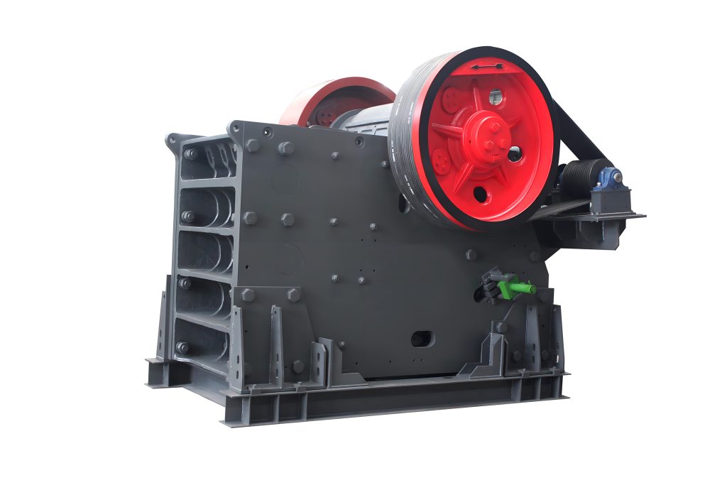
The same work-hardening principle applies to high-manganese steel jaw crusher plates, where repeated impact and compressive loading increase surface hardness while the underlying material retains its toughness. The required manganese grade and heat treatment depend on the crusher’s operating conditions.
This behavior is particularly important because the working surface and the interior of the bar do not necessarily experience the same loading. The surface can become harder through deformation while the underlying material retains greater toughness.
However, work hardening depends on sufficient impact intensity. In applications dominated by abrasive sliding rather than strong impact, manganese steel may not develop the same surface-hardening benefit and can wear relatively quickly.
Martensitic Steel: Balancing Hardness and Toughness
Martensitic blow bars are designed to provide greater hardness and abrasive wear resistance than conventional manganese steel while retaining useful impact resistance.
Their performance is associated with a hardened martensitic matrix. The strength and hardness of this structure help resist surface deformation and abrasive material removal.
Heat treatment is important because the final microstructure affects both hardness and fracture resistance. Excessive hardness without sufficient toughness can increase the risk of chipping or cracking under severe impact.
Martensitic grades are therefore commonly considered for quarrying and recycling applications where a balance between abrasion resistance and impact loading is required.
High-Chromium Iron: Carbide-Based Wear Resistance
High-chromium white iron obtains much of its abrasive wear resistance from hard chromium-rich carbides distributed within a metallic matrix.
These carbides resist penetration and cutting by abrasive mineral particles. Their effectiveness depends on carbide hardness, size, distribution, and the supporting matrix.
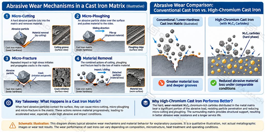
However, hard carbide structures are less tolerant of severe impact than tougher steel-based materials. When tramp metal, oversized feed, or sudden mechanical shocks occur, cracks may initiate around carbide regions or at interfaces between hard phases and the surrounding matrix.
This explains why high-chrome blow bars are generally better suited to controlled secondary or tertiary crushing than to applications with frequent large impacts or uncrushable metal.
Ceramic-Reinforced Composite Blow Bars
Ceramic-reinforced blow bars combine hard ceramic inserts with a metallic supporting matrix. The ceramic phase provides additional resistance to abrasive wear, while the surrounding metal supports the insert and transfers mechanical loads.
The position and distribution of ceramic inserts are important. If the inserts are not adequately supported or the application produces excessive impact loading, local cracking, chipping, or insert detachment may occur.
These composite materials are generally considered for highly abrasive applications with controlled feed size and limited tramp metal. Their suitability must be evaluated against the complete crushing conditions rather than assuming that ceramic reinforcement is always beneficial.
Material Selection Comparison
| Material | Main Wear Resistance Mechanism | Impact Tolerance | Typical Application |
|---|---|---|---|
| Manganese Steel | mpact-induced work hardening | High | Primary crushing and applications with tramp metal risk |
| Martensitic Steel | Hardened metallic matrix | Grade-dependent | Quarrying and recycling |
| High-Chrome Iron | Hard chromium-rich carbides | Lower than tougher steel grades | Controlled secondary and tertiary crushing |
| Ceramic-Reinforced Composite | Ceramic reinforcement supported by a metallic matrix | Application-dependent | Highly abrasive applications with controlled feed |
Material selection should be based on feed size, abrasiveness, tramp metal content, and crushing stage. Hardness alone is not a reliable measure of expected service life.
When to Turn or Replace Blow Bars
Blow bars should be inspected at regular intervals to determine whether they can continue operating, be turned to expose another working face, or require replacement.
Reversible designs allow the unused side of a bar to be brought into service after the original working edge reaches its permitted wear limit. However, not all blow bars are reversible, and turning is only appropriate when the bar geometry and manufacturer’s maintenance procedure permit it.
Several conditions should be checked before deciding whether to continue using a bar:
- Remaining wear section: Measure the remaining material at the specified inspection points rather than relying on overall appearance.
- Cracks and chipping: Check the leading edge, corners, and transitions between the working face and body.
- Mounting condition: Inspect the seating surfaces, locking wedges, and retaining components.
- Rotor balance: Confirm that opposing bars meet the manufacturer’s mass-matching requirements.
The minimum permitted wear section varies with blow bar design and crusher configuration. Replacement limits should be established from the manufacturer’s specified measurement points rather than applying a universal remaining-thickness value.
Opposing blow bars should be installed according to the rotor manufacturer’s specified arrangement and mass-matching requirements. Correct positioning and weight matching help maintain rotor balance and reduce vibration during operation.
Replacing bars too late can expose the rotor body, supporting strips, and retaining components to direct wear. It can also increase the risk of vibration and secondary mechanical damage.
Impact Crusher Blow Bar Manufacturer and Supplier Selection
Choosing a reliable blow bar manufacturer involves more than comparing alloy grades and unit prices. Casting quality, material composition, heat treatment, dimensional accuracy, and rotor compatibility all influence the performance of the finished component.
Manufacturing quality should be evaluated through several technical aspects:
| Quality Control Item | What to Verify | Engineering Importance |
|---|---|---|
| Chemical Composition | Alloy content and material specification | Determines the intended material properties |
| Metallographic Structure | Matrix condition and carbide distribution where applicable | Helps evaluate wear resistance and fracture behavior |
| Heat Treatment | Process records and final material condition | Influences hardness and toughness |
| Casting Quality | Surface condition and internal defect inspection | Reduces the risk of premature cracking |
| Dimensional Inspection | Overall dimensions and mounting geometry | Ensures compatibility with the rotor |
| Weight Verification | Individual and opposing-bar mass | Supports rotor balance |
For replacement impact crusher wear parts, compatibility must be confirmed against the crusher model, rotor arrangement, retaining system, and approved blow bar profile.
A qualified blow bar supplier should also be able to clarify material options, available dimensions, inspection documentation, and replacement arrangements. Purchase price should be evaluated alongside expected wear performance, replacement frequency, and production downtime.
Octa Mach can support inquiries for impact crusher blow bars and related wear components according to equipment requirements and crushing applications. Material selection, component dimensions, and supply arrangements should be reviewed before production to ensure that the replacement parts match the intended operating conditions.
For a broader overview of crusher wear components, including jaw plates, cheek plates, mantles, and bowl liners, see our crusher parts guide for material specifications, wear characteristics, and replacement considerations.
FAQ
Q: What causes uneven wear on impact crusher blow bars?
A:Uneven blow bar wear is commonly associated with inconsistent feed distribution, excessive fines, or off-centre material loading. Inspect the feed chute, rotor width, and crushing chamber for uneven material flow. Correcting feed distribution can help improve wear uniformity and extend the usable life of the blow bars.
Q: Which blow bar material is best for crushing abrasive rock?
A:High-chrome and ceramic-reinforced blow bars offer high abrasion resistance for suitable secondary and tertiary crushing applications. Martensitic steel provides a balance between hardness and impact resistance, while manganese steel is better suited to heavy-impact conditions. Feed size and tramp metal content should be evaluated before selecting an alloy.
Q: How does rotor speed affect impact crusher blow bar wear?
A:Rotor speed affects blow bar peripheral velocity and the impact conditions inside the crushing chamber. Its influence on penetration and wear depends on feed size, material properties, blow bar profile, and crusher configuration. Operating speed should be evaluated against the manufacturer’s recommended range rather than adjusted solely to correct one wear pattern.
Q: When should impact crusher blow bars be turned or replaced?
A:Blow bars should be turned when the working edge reaches its specified wear limit, provided the design allows reversible installation. Replace bars showing structural cracks, severe chipping, or excessive material loss. During replacement, check retaining wedges and ensure opposing bars meet the manufacturer’s rotor balance requirements.