
flotation machine is a mechanical mineral-processing unit that mixes conditioned ore slurry, disperses air into fine bubbles and creates controlled contact between bubbles and selectively hydrophobic mineral particles. The floated mineral–bubble aggregates rise into a froth layer and are removed as concentrate, while non-floating material remains in the pulp and moves to the next cell or tailings stage.
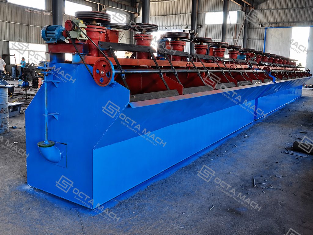
Octa Mach supplies KYF and SF series mining flotation machines with effective cell volumes from 0.7 to 38 m³. The equipment range covers self-aerating and externally aerated configurations for separating copper, lead, zinc, nickel, molybdenum, gold-bearing sulphides and other metallic or non-metallic minerals. Matched cell volume, impeller diameter, rotational speed, air supply and installed motor power allow the equipment to be configured as an energy-saving flotation machine without relying on unsupported fixed energy-reduction claims.
Main Operating Range
| Parameter | Available Range |
| Product series | KYF and SF |
| Effective cell volume | 0.7–38 m³ |
| Reference processing range | 0.2–38, depending on model and series |
| Tank dimensions | 820 × 900 × 950 to 3600 × 3600 × 3400 mm |
| Impeller diameter | 340–880 mm |
| Impeller speed | 191–400 r/min for the published SF range |
| Main motor power | 3–37 kW per published model configuration |
| Scraper motor power | 1.1–1.5 kW |
| Published air requirement | Model-dependent |
| Main applications | Metallic, non-metallic and sulphide-ore flotation |
Published processing values are intended for preliminary model comparison. Actual duty depends on pulp density, particle-size distribution, mineral liberation, flotation time, reagent scheme, air rate, froth depth and the number of roughing, scavenging and cleaning stages.
KYF and SF Flotation Equipment
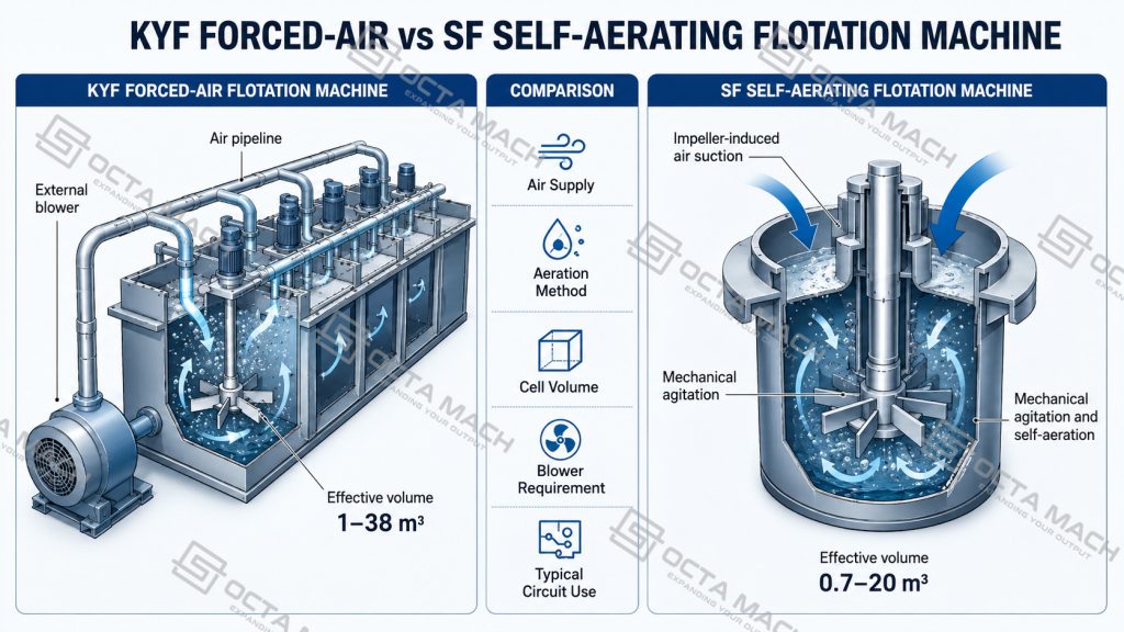
The product range includes two main mechanical flotation cell configurations. They perform the same fundamental separation duty but use different air-supply and circulation arrangements.
KYF Forced-Air Flotation Machine
The KYF series uses a separate air source to deliver air into the pulp. The impeller disperses the supplied air, circulates the slurry and maintains contact between mineral particles and bubbles.
This configuration is suitable where the plant requires:
- independent adjustment of air volume;
- relatively large effective cell volumes;
- stable air distribution across multiple cells;
- integration with a dedicated blower system;
- controlled roughing, scavenging or cleaning duty.
The published KYF range covers 1–38 m³ effective cell volume and impeller motors from 4 to 37 kW.
SF Mechanical Flotation Machine
The SF series combines mechanical agitation with air induction. Its impeller creates pulp circulation and draws air into the cell while the scraper system removes the mineralized froth.
This mechanical flotation machine is available with effective cell volumes from 0.7 to 20 m³. It is suited to small and medium flotation circuits, independent cells and multi-cell arrangements where compact installation and self-aeration are important.
KYF Series Technical Parameters
| Model | Tank Size L × W × H (mm) | Effective Volume (m³) | Reference Capacity | Impeller Motor (kW) | Impeller Diameter (mm) | Scraper Motor (kW) | Required Blower Pressure (kPa) |
| KYF-1 | 1000 × 1000 × 1100 | 1 | 0.2–1 | 4.0 | 340 | 1.1 | ≥12.6 |
| KYF-2 | 1300 × 1300 × 1250 | 2 | 0.4–2 | 5.5 | 410 | 1.1 | ≥14.7 |
| KYF-3 | 1600 × 1600 × 1400 | 3 | 0.6–3 | 7.5 | 480 | 1.5 | ≥19.8 |
| KYF-4 | 1800 × 1800 × 1500 | 4 | 1.2–4 | 11.0 | 550 | 1.5 | ≥19.8 |
| KYF-8 | 2200 × 2200 × 1950 | 8 | 3–8 | 15.0 | 630 | 1.5 | ≥21.6 |
| KYF-16 | 2800 × 2800 × 2400 | 16 | 4–16 | 30.0 | 740 | 1.5 | ≥25.5 |
| KYF-24 | 3100 × 3100 × 2900 | 24 | 4–24 | 30.0 | 800 | 1.5 | ≥30.4 |
| KYF-38 | 3600 × 3600 × 3400 | 38 | 10–38 | 37.0 | 880 | 1.5 | ≥34.3 |
The blower should be selected for the pressure requirement of the chosen cell, total air demand, pipe resistance, elevation and the number of cells operating simultaneously. Blower pressure alone does not define flotation performance.
SF Series Technical Parameters
| Model | Effective Volume (m³) | Tank Size L × W × H (mm) | Impeller Diameter (mm) | Impeller Speed (r/min) | Reference Capacity | Motor Power (kW) | Air Intake | Single Tank Weight (kg) |
| SF-0.7 | 0.7 | 820 × 900 × 950 | 350 | 400 | 0.3–0.9 | 3 / 1.1 | 0.8–1.0 | 805 |
| SF-1.2 | 1.2 | 1100 × 1100 × 1100 | 450 | 312 | 0.6–1.2 | 5.5 / 1.1 | 1.0–1.2 | 1373 |
| SF-2.8 | 2.8 | 1700 × 1600 × 1150 | 550 | 268 | 1.5–3.5 | 11 / 1.5 | 1.0–1.2 | 2138 |
| SF-4 | 4.0 | 1850 × 2050 × 1200 | 650 | 220 | 2–4 | 15 / 1.5 | 1.0–1.2 | 2582 |
| SF-8 | 8.0 | 2200 × 2900 × 1400 | 760 | 191 | 4–8 | 30 / 1.5 | 0.9–1.0 | 4129 |
| SF-10 | 10.0 | 2200 × 2900 × 1700 | 760 | 191 | 5–10 | 30 / 1.5 | 0.9–1.0 | 4486 |
| SF-16 | 16.0 | 2850 × 3800 × 1700 | 760 | 191 | 5–16 | 30 × 2 / 1.5 | 0.9–1.0 | 8320 |
| SF-20 | 20.0 | 2850 × 3800 × 2000 | 760 | 191 | 5–20 | 30 × 2 / 1.5 | 0.9–1.0 | 9828 |
The two motor values shown for the SF range correspond to the published agitation and froth-scraping drive configuration. Final electrical scope should be checked against the approved motor list and plant power supply.
Flotation Cell Selection
A suitable mineral processing flotation machine is selected from the process duty rather than from nominal tank volume alone.
Preliminary Cell-Volume Calculation
The total effective volume can be estimated from:
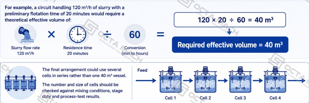
Required effective volume = slurry flow rate × required residence time
An operating allowance should then be considered for level control, froth depth, short-circuiting, process variation and maintenance requirements.
For example, a circuit handling 120 m³/h of slurry with a preliminary flotation time of 20 minutes would require a theoretical effective volume of:
120 × 20 ÷ 60 = 40 m³
The final arrangement could use several cells in series rather than one 40 m³ vessel. The number and size of cells should be checked against mixing conditions, stage duty and process-test results.
The following information should be confirmed before model selection:
- dry-solids throughput in tonnes per hour;
- slurry flow in cubic metres per hour;
- pulp density or solids concentration;
- mineral type and target valuable minerals;
- feed particle-size distribution and liberation size;
- required flotation time;
- roughing, scavenging or cleaning duty;
- expected froth characteristics;
- required number of cells and standby philosophy;
- available blower pressure and airflow for KYF models;
- plant elevation and ambient conditions;
- motor voltage, frequency and protection class.
Flotation Machine Working Principle
A froth flotation machine separates minerals through differences in surface wettability rather than through particle size or density alone.
1. Slurry Conditioning
Ground ore is mixed with water to form pulp. Collectors, frothers, modifiers, activators or depressants are added according to the mineralogy and required separation route.
2. Mechanical Agitation
The rotating impeller keeps solids suspended and circulates slurry through the cell. Sufficient circulation is required to reduce sanding, distribute reagents and bring mineral particles into contact with dispersed air bubbles.
3. Air Dispersion
Air is either induced by the impeller or supplied from an external blower. The rotor and stator break the air stream into smaller bubbles and distribute them through the pulp.
4. Bubble–Particle Attachment
Hydrophobic mineral particles attach to the bubble surfaces. Hydrophilic gangue particles remain in the liquid phase unless their surface properties are changed by the reagent system.
5. Froth Formation and Removal
Mineralized bubbles rise to the top of the flotation cell and form a froth layer. The scraper removes this froth into a concentrate launder. The remaining pulp is discharged or passed into the next flotation stage.
Main Flotation Machine Parts
A complete industrial flotation machine normally contains the following functional assemblies.
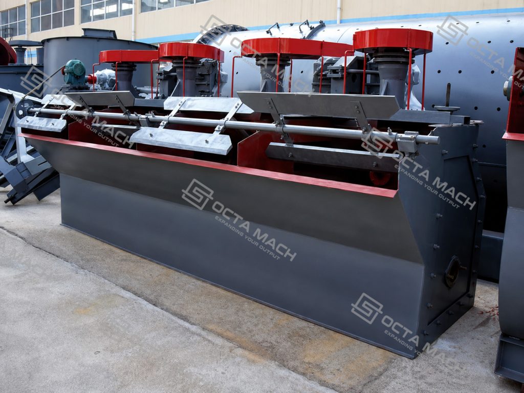
- Tank and pulp-flow passage:The tank retains the slurry and directs inter-cell flow. Its effective volume determines the available residence time together with the actual pulp flow rate.
- Impeller:The impeller supplies mechanical agitation, suspends solids and circulates the pulp. Depending on the flotation-machine type, it also induces air or disperses externally supplied air.
- Stator:The stator controls radial flow around the impeller, stabilizes circulation and helps distribute air through the cell.
- Main shaft and bearing assembly:These components transmit motor torque to the impeller. Alignment, lubrication and bearing condition directly affect vibration and service stability.
- Air-supply system:KYF cells require an external air source selected for the published pressure requirement and complete system resistance. SF cells use the suction generated by the rotating mechanism.
- Froth scraper and concentrate launder:The scraper transfers mineralized froth into the launder at a controlled rate. Scraper speed and froth depth influence concentrate withdrawal and froth stability.
- Level and discharge arrangement:The pulp level determines froth depth and effective cell volume. Stable level control is important in multi-cell roughing and cleaning circuits.
Energy-Saving Configuration
An energy-efficient flotation machine should not be selected from motor power alone. Useful energy is determined by whether the cell can provide the required suspension, air dispersion and residence time without excessive agitation or oversized installed power.
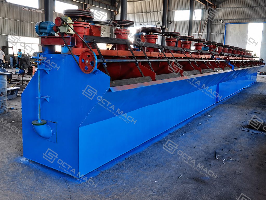
The main energy-control points are:
- selecting cell volume from actual slurry flow and required flotation time;
- matching impeller diameter and speed to pulp density and particle size;
- avoiding excessive air pressure or air volume;
- using larger cells where they reduce unnecessary numbers of small drives;
- maintaining correct rotor–stator clearance;
- controlling froth depth and scraper operation;
- preventing sanding, blocked air passages and worn impeller components;
- matching the blower to the complete KYF cell bank rather than one cell in isolation.
For this reason, “energy-saving” should be treated as a system-selection result. No fixed reduction percentage should be stated without comparative test data under the same ore and operating conditions.
Mineral Processing Applications
The flotation equipment is designed for ores whose valuable minerals can be selectively rendered hydrophobic through reagent conditioning.
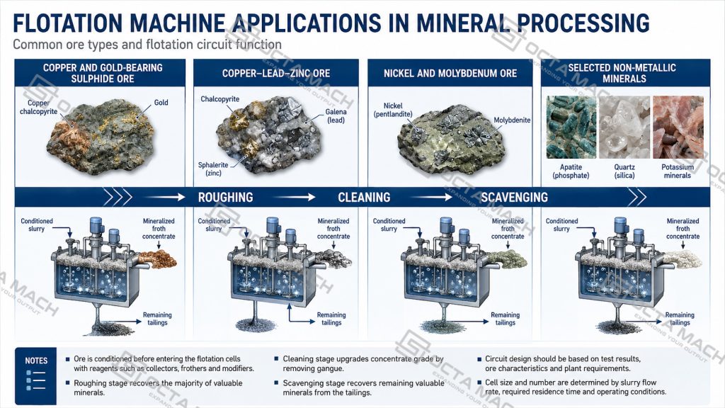
Copper and Gold-Bearing Sulphide Ore
After crushing, grinding and classification, the conditioned slurry enters a bank of ore flotation machines for roughing. Rougher concentrate may pass through one or more cleaning stages, while rougher tailings can be treated in scavenger cells before final discharge.
Copper–Lead–Zinc Separation
Complex polymetallic ore commonly requires staged reagent control and selective flotation. Separate cell banks may be used for copper, lead and zinc recovery, with regrinding or additional conditioning between stages when liberation requires it.
Nickel and Molybdenum Ore
Mechanical flotation can be used for sulphide nickel and molybdenum separation where fine-bubble dispersion, stable suspension and controlled froth removal are required.
Non-Metallic Minerals
The same flotation principle can be applied to selected non-metallic minerals when their surface properties can be modified sufficiently for selective bubble attachment.
Actual recovery and concentrate grade depend on mineralogy, liberation size, reagent regime and circuit design. The machine does not independently guarantee a fixed metallurgical result.
Flotation Machine in a Complete Beneficiation Circuit
A typical flotation plant may include:
Ore bin → feeder → crusher → vibrating screen → ball mill → classifier or hydrocyclone → agitation tank → flotation cells → thickener → filter press.
The flotation machine is therefore not an isolated separator. Feed preparation upstream determines liberation and particle-size distribution, while dewatering equipment downstream determines final concentrate handling.
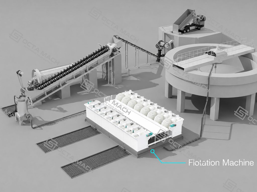
In copper–lead–zinc processing, several flotation banks may be installed for differential separation. Pumps, conditioning tanks and regrinding equipment can be positioned between the banks according to the flowsheet.
Manufacturing and Inspection
Before delivery, the equipment should be checked at component, assembly and functional levels.
Key inspection points include:
- tank dimensions, weld appearance and structural consistency;
- shaft machining and bearing fit;
- impeller and stator dimensions;
- rotor–stator clearance;
- shaft alignment and manual rotation;
- motor, coupling and transmission alignment;
- scraper-drive operation;
- air-pipe connection and sealing;
- lubrication arrangement;
- protective guards and access platforms;
- no-load rotation, vibration and abnormal noise;
- model plate and component identification.
Where numerical acceptance limits are not stated in the approved technical specification, inspection should follow the factory procedure and project requirements rather than an invented universal tolerance.
FAQ
Q: What is the difference between a flotation machine and a flotation cell?
A: A flotation cell is the individual tank in which aeration, agitation and froth separation occur. A flotation machine may refer to one cell or a complete multi-cell assembly with drives, scrapers, launders and air-supply components.
Q: What is the difference between KYF and SF flotation machines?
A: KYF models use externally supplied air and provide effective volumes from 1 to 38 m³. SF models combine mechanical agitation with air induction and cover effective volumes from 0.7 to 20 m³.
Q: How is flotation-machine capacity selected?
A: Capacity is selected from actual slurry flow, solids concentration, required flotation time, mineral liberation, air demand and circuit duty. Published ranges are suitable for preliminary comparison but do not replace mineral test work.
Q: Can one flotation machine process copper, gold, lead and zinc ores?
A: The same mechanical equipment principle can be used, but the reagent system, cell arrangement, flotation time and cleaning stages must be matched to each ore. Complex copper–lead–zinc ore normally requires staged selective flotation.
Q: Why does a KYF flotation machine require a blower?
A: The KYF mechanism disperses externally supplied air rather than relying only on self-suction. The blower must provide enough pressure and flow for the selected cells, piping resistance and plant elevation.