
An energy-saving ball mill is a horizontal grinding machine used to reduce crushed ore and industrial minerals into a controlled fine product through the impact and abrasion of grinding media inside a rotating cylinder. It is commonly installed after primary or secondary crushing and before flotation, magnetic separation, gravity concentration, leaching or other beneficiation stages. Available for wet or dry grinding, the Octa Mach ball mill combines a heavy-duty rotating shell, replaceable liners, graded grinding media and a geared drive system. Its roller-bearing support and optimized discharge arrangement help reduce running resistance and maintain stable continuous grinding under correctly selected operating conditions.
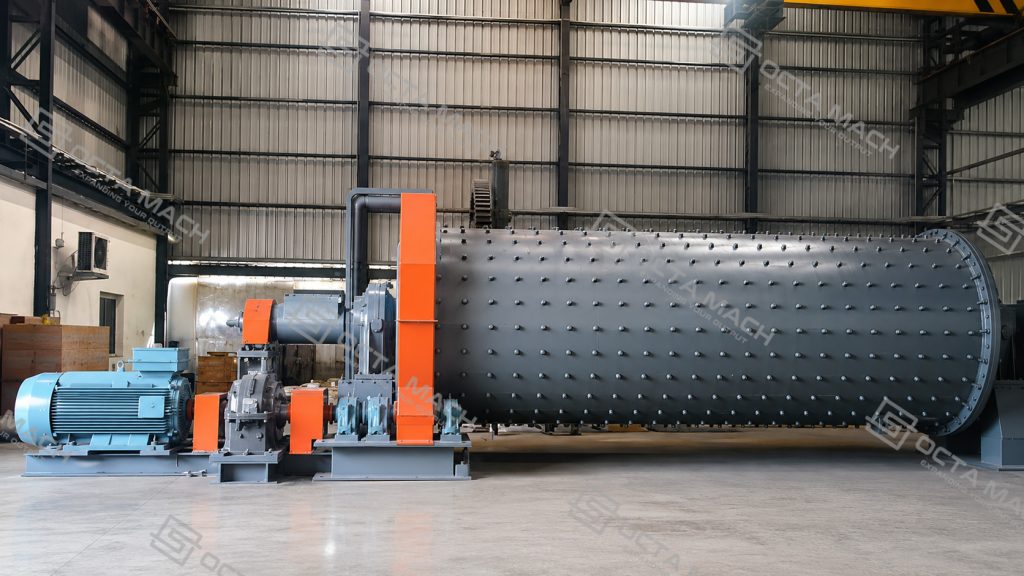
Main Operating Range
| Parameter | Available Range |
| Feed size | ≤25 mm |
| Discharge size | 0.074–0.89 mm, depending on model and grinding circuit |
| Processing capacity | 0.65–90 t/h |
| Motor power | 15–800 kW |
| Cylinder speed | 18–42 r/min |
| Grinding method | Wet or dry grinding |
| Main discharge options | Overflow or grate discharge |
| Main applications | Metallic ore beneficiation, industrial minerals, cement and building materials |
The current Octa Mach ball mill range covers models from Φ900 × 1800 to Φ3200 × 4500. Actual throughput and final particle size depend on material hardness, feed grading, circulating load, ball charge, liner condition and classifier performance.
Complete Ball Mill Model and Specification Overview
The complete Octa Mach ball mill range covers models from Φ900 × 1800 to Φ3200 × 4500, with published motor power from 15 to 800 kW and preliminary processing capacities covering 0.65–90 t/h across the listed model range. The specification chart below consolidates cylinder speed, ball load, feed size, discharge size, capacity, motor power and equipment weight to support rapid comparison during early-stage equipment selection.
Project teams should use this overview to identify an appropriate mill-size category before confirming the final grinding circuit, classifier arrangement, drive power and auxiliary-system scope.
| Model | Cylinder Speed (r/min) | Ball Load (t) | Feed Size (mm) | Discharge Size (mm) | Capacity (t/h) | Motor Power (kW) | Weight (t) |
|---|---|---|---|---|---|---|---|
| Φ900×1800 | 42 | 1.4 | ≤20 | 0.075–0.89 | 0.65–2 | 15 | 3.6 |
| Φ900×2100 | 41 | 1.7 | ≤15 | 0.075–0.83 | 0.7–3.5 | 18.5 | 3.9 |
| Φ900×3000 | 41 | 2.5 | ≤20 | 0.075–0.89 | 1.1–3.5 | 22 | 4.5 |
| Φ1200×2400 | 36 | 3.5 | ≤25 | 0.075–0.6 | 1.5–4.7 | 30 | 11.5 |
| Φ1200×2800 | 36 | 4.5 | ≤25 | 0.075–0.6 | 1.5–5 | 37 | 13 |
| Φ1200×4500 | 32 | 5.5 | ≤25 | 0.074–0.4 | 1.6–5.8 | 55 | 13.8 |
| Φ1500×3000 | 31 | Pending confirmation | ≤25 | 0.074–0.4 | 2–7 | 75 | 17 |
| Φ1500×3500 | 31 | Pending confirmation | ≤25 | 0.075–0.4 | 3–8.5 | 75 | 17.5 |
| Φ1500×4500 | 27 | 10.5 | ≤25 | 0.074–0.4 | 3.5–8 | 110 | 21 |
| Φ1500×5700 | 27 | 15 | ≤25 | 0.074–0.4 | 3.5–10 | 130 | 24.7 |
| Φ1830×3000 | 26 | 18 | ≤25 | 0.074–0.4 | 4–12 | 160 | 28 |
| Φ1800×3600 | 26 | 10.6–11.35 | ≤25 | 0.075–0.4 | 5–13 | 160 | 33.5 |
| Φ1830×4500 | 26.5 | 12 | ≤25 | 0.075–0.6 | 5.5–20 | 185 | 35 |
| Φ1830×7000 | 26 | 25 | ≤25 | 0.074–0.4 | 6.5–22 | 210 | 36 |
| Φ2100×3600 | 24 | 14–15.2 | ≤25 | 0.075–0.4 | 15–30 | 185 | 46.8 |
| Φ2200×5500 | 21 | 30 | ≤25 | 0.074–0.4 | 10–20 | 245 | 48.5 |
| Φ2200×6500 | 21 | 31 | ≤25 | 0.074–0.4 | 14–50 | 380 | 52.8 |
| Φ2200×7500 | 21 | 33 | ≤25 | 0.074–0.4 | 16–50 | 380 | 56 |
| Φ2400×3000 | 20.6 | 15.5–16.6 | ≤25 | 0.075–0.4 | 15–55 | 245 | 59 |
| Φ2400×4500 | 21 | 30 | ≤25 | 0.074–0.4 | 15–60 | 380 | 65 |
| Φ2700×3600 | 20.6 | 39 | ≤25 | 0.074–0.4 | 20–70 | 400 | 91.3 |
| Φ2700×4000 | 20.7 | 40 | ≤25 | 0.074–0.4 | 20–80 | 400 | 94 |
| Φ2700×4500 | 20.7 | 48 | ≤25 | 0.074–0.4 | 20–90 | 430 | 102 |
| Φ3200×4500 | 18 | 65 | ≤25 | 0.075–0.4 | Project-dependent | 800 | 137 |
Technical Selection Note:
The published values are intended for preliminary model comparison and should not be interpreted as guaranteed operating output. Actual throughput and final product size depend on material hardness, feed-size distribution, target P80, moisture content, grinding concentration, ball charge, media grading, liner condition, circulating load and classifier efficiency.
Final equipment selection should be confirmed according to:
Material properties → Maximum feed size → Required capacity → Target product size → Wet or dry grinding → Overflow or grate discharge → Ore hardness → Classifier arrangement → Site voltage → Installation conditions.
Applications and Grinding Duties
After reviewing the model range, the next step is to match the mill with the actual grinding duty. Ball mills are used where crushed feed must be reduced to a finer and more uniform particle size before downstream treatment.
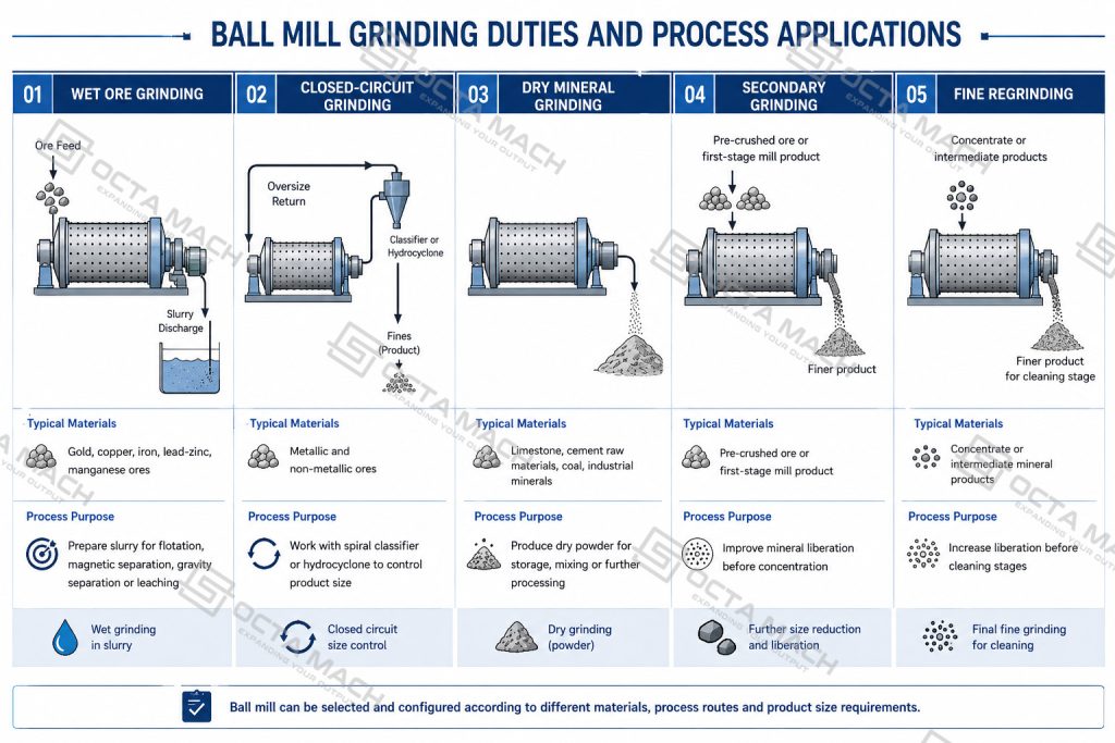
Octa Mach ball mills are available for wet and dry grinding, with overflow or grate discharge configurations selected according to the material, target particle size and downstream process. The mill can be integrated with spiral classifiers or hydrocyclones to maintain stable product-size control in closed-circuit grinding systems.
Ball Mill Types and Process Selection
Ball mill configuration should be selected according to the material condition, target product size, downstream process and required discharge rate. Wet or dry grinding defines the material-handling method, while overflow or grate discharge affects residence time, product fineness and throughput.
| Ball Mill Type | Operating Principle | Main Advantage | Suitable Duty |
| Wet Ball Mill | Water is added to form a pumpable slurry | Easy integration with classifiers, flotation and other wet processes | Metallic ore beneficiation |
| Dry Ball Mill | Material is ground without process water | Produces dry powder and avoids slurry handling | Cement, limestone, coal and industrial minerals |
| Overflow Ball Mill | Product leaves through the hollow discharge trunnion as the material level rises | Longer residence time and relatively fine product | Secondary grinding and fine grinding |
| Grate Discharge Ball Mill | Ground material passes through a grate and is lifted out of the mill | Faster discharge and reduced unnecessary retention | Primary grinding and higher-throughput circuits |
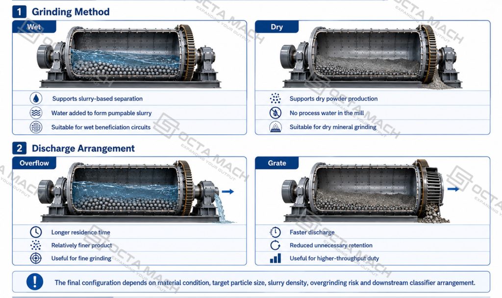
Overflow and grate mills should not be selected only by expected capacity. The required particle-size distribution, slurry density, risk of overgrinding and downstream classifier arrangement must also be reviewed.
Energy-Saving and Operating Features
| Design Feature | Engineering Function | Operating Benefit |
| Double-row self-aligning roller-bearing support | Reduces sliding resistance at the main bearing position | Lower starting and running resistance |
| Optimized cylinder speed | Maintains effective media lifting and cascading | More stable impact and abrasion |
| Grate discharge option | Accelerates removal of correctly ground material | Reduces unnecessary retention and overgrinding |
| Replaceable liner system | Protects the shell and controls media lifting | Easier wear-part replacement and grinding adjustment |
| Large-gear transmission | Transfers motor torque to the rotating shell | Reliable continuous operation |
| Wet and dry configurations | Matches different materials and process routes | Wider application flexibility |
For comparable operating conditions, the roller-bearing configuration can reduce no-load energy consumption compared with conventional sliding-bearing arrangements. An optimized forced-discharge design can also improve material discharge efficiency and increase effective throughput. Actual energy savings and capacity improvement depend on mill size, material characteristics, ball charge and operating conditions.
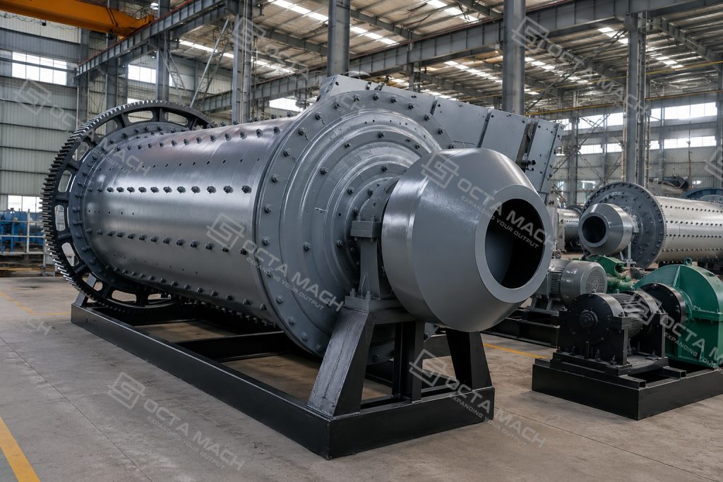
Ball Mill Structure and Working Principle
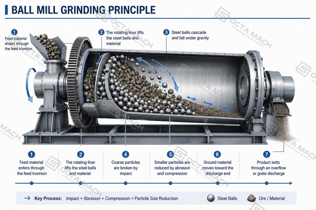
The ball mill mainly consists of a feeding device, hollow shaft, bearing supports, rotating cylinder, liner plates, grinding media, discharge device, large gear, reducer, motor and electrical control system.
Material enters the rotating cylinder through the feed end. As the shell rotates, the liner profile lifts the grinding media and material to a controlled height. The media then falls or rolls through the charge, breaking the feed through repeated impact, compression and abrasion. The ground material moves toward the discharge end and leaves through an overflow or grate arrangement.
The cylinder operates below its critical speed so that the grinding media continues to cascade and tumble instead of remaining centrifuged against the shell. Larger-diameter mills generally operate at lower rotational speeds, while the final operating speed must maintain sufficient lifting action without causing excessive impact, liner wear or energy consumption.
Grinding Media and Liner Configuration
Larger steel balls provide stronger impact for coarse feed, while smaller media increase the number of contact points required for fine grinding. A practical grinding charge normally combines several ball sizes rather than using a single diameter.
| Selection Item | Main Effect |
| Ball diameter and grading | Controls impact force and fine-grinding contact area |
| Ball material and hardness | Affects wear rate, breakage and product contamination |
| Filling ratio | Influences power draw, media movement and mill capacity |
| Liner material and profile | Controls ball lifting height and protects the shell |
| Slurry concentration | Affects material transport and grinding efficiency |
| Media wear condition | Changes the effective charge and product-size distribution |
Common industrial grinding-ball diameters may include approximately 40, 60, 80, 100 and 120 mm. The final media grading should be selected according to mill diameter, feed size, material hardness and required product size.
Ball Mill in a Complete Grinding Circuit
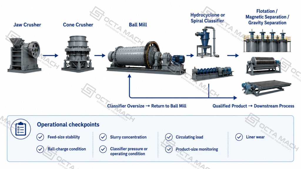
A typical closed-circuit grinding system may be arranged as:
Jaw Crusher → Cone Crusher → Ball Mill → Spiral Classifier or Hydrocyclone → Flotation / Magnetic Separation / Gravity Separation.
The classifier separates particles according to size. Oversized material returns to the ball mill for further grinding, while correctly ground material moves to the next beneficiation stage. This arrangement provides more stable particle-size control and reduces unnecessary overgrinding.
Manufacturing Inspection and Delivery
Ball mill manufacturing and release should focus on the components that directly affect alignment, transmission stability and continuous operation.
| Inspection Item | Main Control Point |
| Cylinder fabrication | Shell roundness, weld quality and dimensional consistency |
| Hollow shaft and bearing support | Machining accuracy, fit and alignment |
| Large gear installation | Radial runout, tooth contact and gear-mesh condition |
| Liner installation | Correct fit, fastening and internal profile |
| Drive system | Motor, reducer, coupling and transmission alignment |
| No-load trial run | Rotation stability, bearing temperature, vibration and abnormal noise |
| Technical documents | General arrangement drawing, foundation data, motor information and operating instructions |
Final equipment configuration, foundation loads, motor voltage, auxiliary systems and spare-parts scope should be confirmed before production.
Information Required for Ball Mill Selection
To prepare a technical selection, provide the following project conditions:
Material → maximum feed size → required capacity → target product size → wet or dry grinding → discharge type → ore hardness → classifier arrangement → site voltage → installation conditions.
Octa Mach will use these inputs to confirm the suitable mill model, drive power, grinding circuit and equipment configuration.
FAQ
Q: How is the correct ball mill model selected?
A: Model selection should be based on material hardness, maximum feed size, required throughput, target P80, wet or dry operation, discharge type, classifier arrangement and site power conditions.
Q: What is the difference between a wet ball mill and a dry ball mill?
A: A wet ball mill grinds material with water to form slurry for flotation, magnetic separation or gravity concentration. A dry ball mill produces powder without process water and is commonly used for cement, limestone, coal and industrial minerals.
Q: When should an overflow or grate discharge ball mill be used?
A: Overflow discharge is generally selected for longer residence time and finer grinding. Grate discharge removes ground material more quickly and is suitable where higher throughput and reduced overgrinding are required.
Q: Can the published ball mill capacity be treated as guaranteed output?
A: No. Published capacity is for preliminary comparison. Actual output depends on ore hardness, feed grading, target product size, ball charge, liner condition, slurry concentration, circulating load and classifier efficiency.
Q: What information is required before final ball mill configuration?
A: The required data includes material composition, feed size, capacity, target product size, Bond Work Index or hardness, grinding method, discharge type, classifier type, voltage, installation conditions and upstream and downstream equipment.