
A high-weir spiral classifier separates ore slurry, a mixture of water and ground mineral particles, according to particle size and settling speed. It is commonly installed after a ball mill in mineral-processing plants handling gold, copper, iron ore and other ores. Fine particles remain suspended in the water and flow over the discharge weir to the next separation stage, while coarser particles settle to the bottom and are lifted by the rotating spiral for discharge or return to the ball mill for further grinding.
The machine consists of an inclined steel tank, one or two slow-speed spiral assemblies, a drive system, lifting mechanism, lower bearing support, overflow weir and coarse-particle discharge end. This arrangement helps maintain a controlled grinding circuit and prevents oversized particles from entering downstream flotation, magnetic separation or gravity-concentration equipment.
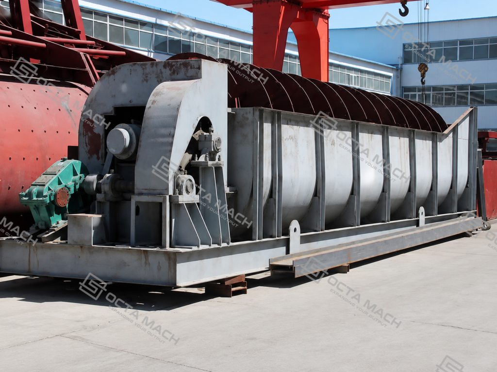
The FG and 2FG series are configured as single- and double-spiral machines. The confirmed product range covers spiral diameters from 750 to 3,000 mm, tank lengths from 5,500 to 12,500 mm, overflow capacities from 65 to 1,785 t/24 h, and returned-sand capacities up to 23,400 t/24 h. These models are mainly used as a high weir spiral classifier in closed-circuit grinding, ore-pulp classification, desliming, washing and partial dewatering duties.
Main Operating Range
| Parameter | Confirmed Range |
| Equipment type | High-weir spiral classifier |
| Model range | FG7.5–FG30 and 2FG12–2FG30 |
| Spiral arrangement | Single or double spiral |
| Spiral diameter | 750–3,000 mm |
| Tank length | 5,500–12,500 mm |
| Spiral speed | 2.0–10 r/min |
| Returned-sand capacity | 340–23,400 t/24 h |
| Overflow capacity | 65–1,785 t/24 h |
| Main drive power | 3–22 kW per drive |
| Lifting motor power | Manual or 1.5–4 kW per lifting unit |
| Equipment weight | 2.7–73 t |
Published capacities are equipment ratings rather than guaranteed separation results. Actual overflow size, circulating load and classification performance depend on feed size distribution, solids concentration, mineral density, slurry viscosity, feed stability and the required cut size.
Technical Parameters
For double-spiral models, values marked “×2” indicate two drive or lifting units.
| Model | Spiral Diameter (mm) | Tank Length (mm) | Spiral Speed (r/min) | Returned Sand (t/24 h) | Overflow (t/24 h) | Main Drive (kW) | Lift Drive (kW) | Weight (t) |
| FG7.5 | 750 | 5,500 | 6–10 | 340–570 | 65 | 3 | Manual | 2.7 |
| FG10 | 1,000 | 6,500 | 5.0–8.0 | 675–1,080 | 110 | 4 | Manual | 4.43 |
| FG12 | 1,200 | 6,500 | 5.0–8.0 | 1,170–1,870 | 155 | 5.5 | 1.5 | 8.7 |
| FG15 | 1,500 | 8,400 | 4.0–6.0 | 1,830–2,740 | 235 | 7.5 | 2.2 | 12.5 |
| FG20 | 2,000 | 8,400 | 4.0–6.0 | 3,240–5,400 | 400 | 11 | 2.8 | 20.5 |
| FG24 | 2,400 | 9,210 | 3.6 | 4,650–7,450 | 580 | 15 | 3.0 | 25.6 |
| FG30 | 3,000 | 12,500 | 3.2 | 11,625 | 890 | 22 | 4.0 | 37.7 |
| 2FG12 | 1,200 | 6,500 | 5.0–8.0 | 2,340–3,740 | 310 | 5.5 × 2 | 1.5 × 2 | 14.0 |
| 2FG15 | 1,500 | 8,400 | 4.0–6.0 | 3,660–5,480 | 470 | 7.5 × 2 | 1.5 × 2 | 21.1 |
| 2FG20 | 2,000 | 8,400 | 3.0–5.5 | 7,780–11,880 | 800 | 11 × 2 | 2.8 × 2 | 36.5 |
| 2FG24 | 2,400 | 9,210 | 3.6 | 13,600 | 1,160 | 15 × 2 | 3 × 2 | 46.8 |
| 2FG30 | 3,000 | 12,500 | 2.0–3.2 | 14,600–23,400 | 1,785 | 22 × 2 | 4 × 2 | 73.0 |
Spiral Classifier Working Principle
The spiral classifier working principle combines gravity sedimentation with mechanical lifting.
Ore pulp enters the lower portion of the inclined tank and forms a settling pool. Particles with lower settling velocities remain suspended in the upper slurry layer and move toward the overflow weir. Larger or denser particles settle to the tank bottom, where the slowly rotating spiral blades move them toward the elevated discharge end.
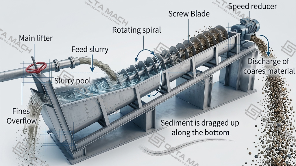
The process produces two main streams:
- Fine-particle overflow: suspended fines and process water discharged over the overflow weir.
- Returned sand: settled coarse solids lifted by the spiral and discharged from the upper end.
The rotating spiral also keeps the settling bed mobile and transports coarse solids continuously. It does not perform primary grinding and should not be confused with a spiral concentrator or spiral chute, which separate minerals mainly according to density in a flowing film.
In mineral-processing circuits, the spiral classifier is normally installed after grinding and before flotation, magnetic separation, gravity separation or other downstream treatment stages.
Main Components
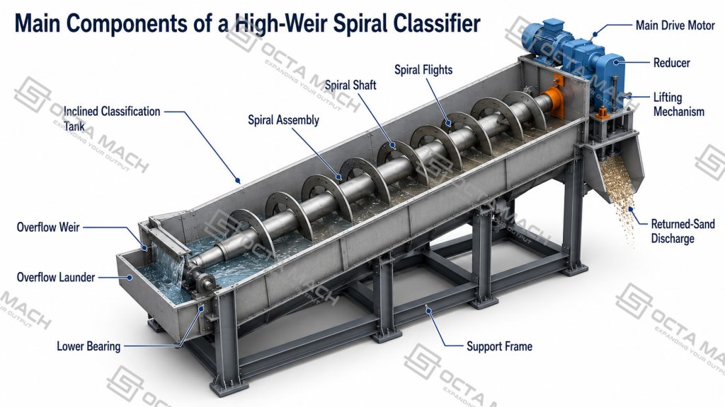
Inclined Classification Tank:The tank provides the settling area required for particle classification. Its length, width, slope, pulp depth and overflow-weir arrangement influence residence time and the effective pool area.
Spiral Assembly:The shaft and spiral flights transport settled solids toward the discharge end. FG models use one spiral, while 2FG models use two parallel spirals to increase sand-return and overflow duty.
Transmission System:The motor, reducer, coupling and shaft drive the spiral at a controlled low speed. Depending on model, confirmed speeds range from 2.0 to 10 r/min.
Lifting Mechanism:The lifting device raises the spiral during shutdown, inspection or restart. Small models may use manual lifting, while larger units use dedicated lifting motors.
Overflow Weir:The overflow-weir position controls the slurry-pool depth. Any adjustment affects settling area, overflow concentration and the effective separation size, so it should be coordinated with feed conditions rather than changed in isolation.
Lower Bearing and Support Structure:The lower bearing supports the submerged end of the spiral shaft. Because it operates close to abrasive slurry, lubrication, sealing condition, alignment and wear inspection are important maintenance points.
Spiral Classifier in a Closed-Circuit Grinding System
A ball mill spiral classifier is commonly installed after a wet ball mill to form a closed grinding circuit:
Ball Mill Discharge → Spiral Classifier → Fine Overflow to the Next Process.
Settled Coarse Sand → Returned to the Ball Mill.
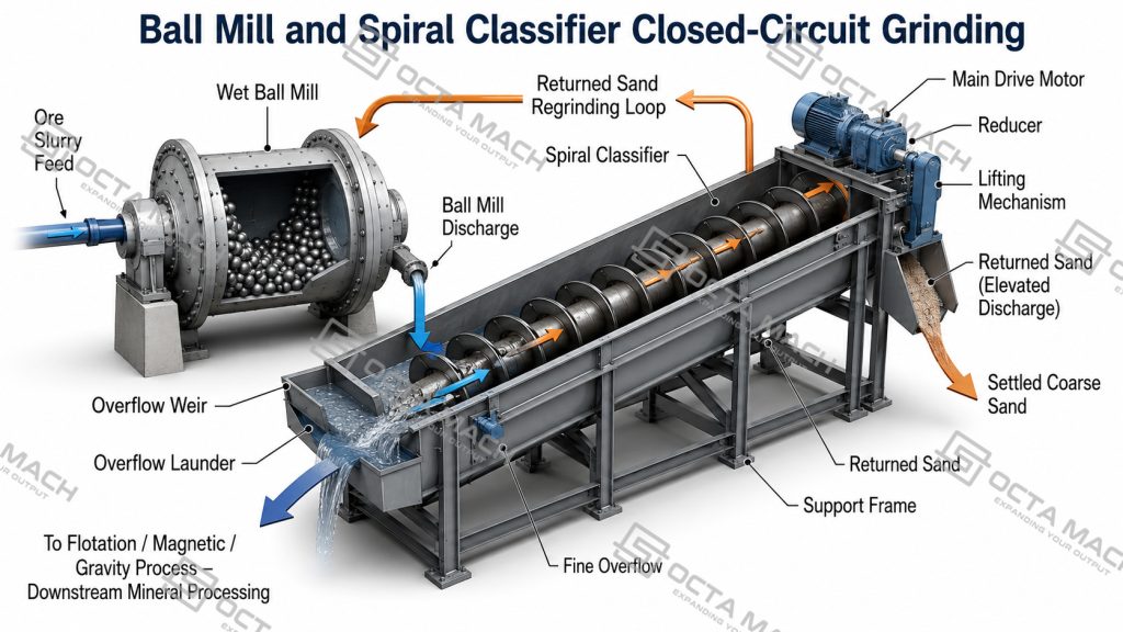
This arrangement prevents adequately ground material from remaining unnecessarily in the mill while returning coarse particles for further size reduction. The classifier therefore helps control the particle-size distribution supplied to flotation, magnetic separation, gravity concentration or leaching.
A closed-circuit grinding spiral classifier should be selected by both overflow duty and returned-sand load. Choosing only by nominal overflow capacity can result in insufficient spiral conveying capacity when the grinding circuit carries a high circulating load.
Single and Double Spiral Classifiers
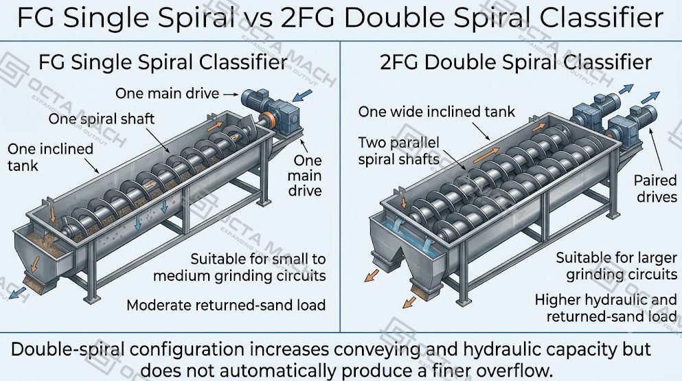
| Configuration | Main Characteristic | Suitable Duty |
| FG single spiral classifier | One spiral assembly and one main drive | Small to medium grinding circuits and moderate sand-return loads |
| 2FG double spiral classifier | Two parallel spirals with paired drives | Higher overflow rates, larger circulating loads and larger grinding circuits |
| High-weir arrangement | Overflow weir positioned to maintain a defined settling pool | General coarse-to-medium mineral-pulp classification |
| Powered spiral lifting | Motorized lifting for larger machines | Maintenance, shutdown and restart of medium and large units |
The double-spiral design does not automatically produce a finer overflow. Its principal advantage is increased conveying and hydraulic capacity. Separation size remains dependent on pulp conditions, settling area, weir setting and operating control.
Spiral Classifier Selection
Correct spiral classifier model selection begins with process duty rather than spiral diameter alone.
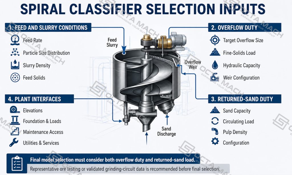
Ore and Feed Conditions
Confirm:
- Feed solids rate and slurry flow
- Feed particle-size distribution
- Maximum particle size
- Pulp solids concentration
- Mineral and gangue density
- Clay, slime and viscosity levels
- Required overflow size
A gold, iron, copper or manganese circuit may use similar equipment, but the selected operating point can differ substantially because settling behavior changes with mineral density, grind size and slurry rheology.
Overflow Duty
Overflow capacity must cover the expected hydraulic and fine-solids load. It should also provide sufficient allowance for normal feed fluctuations without causing excessive coarse-particle carryover.
Returned-Sand Load
The spiral must convey the actual settled load back to the ball mill or discharge point. This becomes especially important in closed circuits with a high circulating load.
Installation Interfaces
Selection must also confirm:
- Ball-mill discharge elevation
- Gravity-flow route into the classifier
- Returned-sand discharge position
- Overflow-pipe or launder elevation
- Foundation load and tank support
- Space for spiral lifting
- Access to the drive and lower bearing
- Slurry-pump duty downstream
Process testing or validated grinding-circuit data should be used before final equipment selection. Generic ore names alone are not sufficient for sizing.
Applicable Materials and Process Duties
The mineral processing spiral classifier can be incorporated into circuits handling metallic ores and selected non-metallic minerals after crushing and grinding.
Typical duties include:
- Gold-ore grinding and classification
- Iron-ore and magnetite circuits
- Copper, lead-zinc and manganese ore processing
- Quartz, feldspar and silica-sand classification
- Ore-pulp desliming before concentration
- Washing of mineral sand and fine aggregates
- Partial dewatering of settled coarse solids
- Separation of sand from fine mud
The equipment receives slurry or ground particulate feed. Hard rocks such as granite, basalt, river pebbles and diabase must first be reduced by crushing and, where required, grinding; they are not fed into the classifier as untreated large rock. The material reference page in the catalogue includes ores and rocks such as iron ore, manganese ore, copper ore, quartz, feldspar, limestone and basalt, but their hardness data describe upstream comminution behavior rather than classifier capacity.
Operating Variables
| Variable | Effect on Classification |
| Feed rate | Excessive flow can shorten settling time and carry coarse particles into the overflow |
| Pulp density | Higher solids concentration can increase hindered settling and shift the effective separation size |
| Spiral speed | Controls agitation and coarse-solids transport; excessive speed may disturb the settling zone |
| Overflow-weir height | Changes pool depth and effective settling area |
| Tank slope | Affects slurry depth, transport distance and returned-sand discharge |
| Feed-size distribution | Determines the amount of coarse material that must be lifted and returned |
| Returned-sand load | Directly affects required spiral diameter, number of spirals and drive duty |
These variables interact. A change in feed rate can alter pool conditions, returned-sand load and overflow quality at the same time. Stable feed preparation is therefore usually more effective than frequent adjustment after the slurry enters the tank.
Spiral Classifier Supply and Technical Support
We provide FG single-spiral classifiers and 2FG double-spiral classifiers for mineral grinding, ore-pulp classification, desliming, washing and partial dewatering duties. Available models cover spiral diameters from 750 to 3,000 mm, with both manual and motorized lifting configurations for different plant capacities and maintenance requirements.
Our supply scope can include:
- Spiral classifier equipment matched to ball-mill discharge and circulating-load requirements
- Single- or double-spiral configuration selection
- Drive, lifting mechanism, tank, spiral shaft and supporting components
- Overflow and returned-sand interface review
- Equipment layout and foundation-reference information
- Spare and wear-part supply
- Technical documents, operating instructions and maintenance guidance
- Installation, commissioning and operator-training support according to project scope
Model selection is based on feed solids, slurry flow, pulp density, target overflow size, returned-sand load and plant layout. This allows the classifier to be integrated into closed-circuit grinding systems, flotation preparation lines, magnetic-separation circuits, gravity-processing plants and other wet mineral-processing applications without relying only on nominal machine capacity.
FAQ
Q: What is the capacity of the FG spiral classifier range?
A: Confirmed overflow capacity ranges from 65 to 1,785 t/24 h, while returned-sand capacity ranges from 340 to 23,400 t/24 h, depending on the model.
Q: What is the difference between FG and 2FG models?
A: FG models use one spiral assembly. The 2FG series uses two spirals and paired drives to handle higher hydraulic and returned-sand loads.
Q: Can a spiral classifier work with a ball mill?
A: Yes. It is commonly used with a wet ball mill in closed-circuit grinding, returning settled coarse particles while sending fine overflow to the next processing stage.
Q: Can the machine classify gold, iron and copper ore?
A: Yes, after the ore has been crushed and ground into slurry. Final model selection must be based on solids rate, slurry flow, feed size, density and target overflow size.
Q: Does the listed capacity guarantee a specific overflow particle size?
A: No. Catalogue capacity is a nominal equipment rating. Actual separation depends on feed distribution, pulp density, settling behavior, weir setting, spiral speed and circuit stability.