
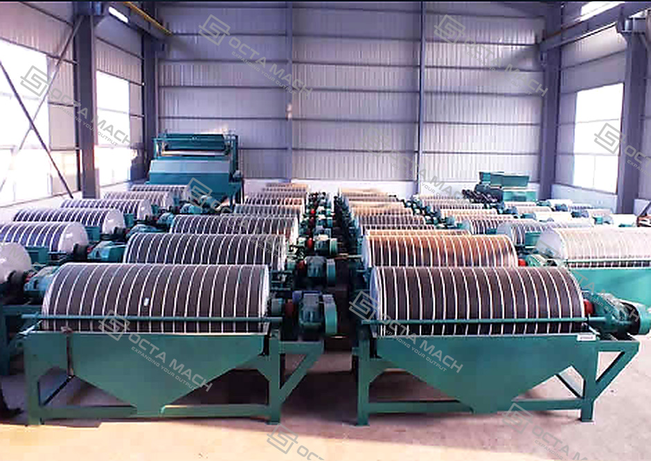
A magnetic separator is mineral-processing equipment used to separate magnetic minerals from non-magnetic gangue by applying a controlled magnetic field to dry ore or mineral slurry. A typical wet-drum unit consists of a non-magnetic rotating drum shell, an internal permanent magnetic system, a feed tank, concentrate and tailings launders, a drive assembly and a supporting frame. Magnetic particles are attracted to the drum surface and carried to the concentrate outlet, while non-magnetic particles leave through the tailings discharge.
This magnetic separator machine is mainly used for magnetite concentration, iron ore beneficiation, recovery of magnetic minerals and removal of magnetic impurities. Its continuous drum structure supports stable processing with relatively low installed power. Final separation performance depends on mineral magnetic susceptibility, feed size, liberation, slurry concentration, drum speed and magnetic field intensity.
Main Operating Range
The CTB wet-drum magnetic separation equipment series shown in the product catalogue covers nine models with capacities from 10 to 200 t/h. The published drum diameter, drum length, feed size and power data provide the main basis for preliminary model comparison.
| Parameter | Published Range |
| Machine type | CTB wet-drum magnetic separator |
| Drum diameter | 600–1,500 mm |
| Drum length | 1,200–5,000 mm |
| Feed size | 0–2 mm or 0–3 mm |
| Drum speed | Up to 15–35 r/min, depending on model |
| Processing capacity | 10–200 t/h |
| Motor power | 1.5–11 kW |
| Main process | Wet magnetic separation |
| Typical application | Magnetite and strongly magnetic mineral feeds |
CTB Magnetic Separator Technical Parameters
| Model | Drum Diameter (mm) | Drum Length (mm) | Drum Speed (r/min) | Feed Size (mm) | Capacity (t/h) | Motor Power (kW) |
| CTB6012 | 600 | 1,200 | ≤35 | 0–2 | 10–20 | 1.5 |
| CTB6018 | 600 | 1,800 | ≤35 | 0–2 | 15–30 | 2.2 |
| CTB7518 | 750 | 1,800 | ≤35 | 0–2 | 20–45 | 2.2 |
| CTB9018 | 900 | 1,800 | ≤35 | 0–3 | 40–60 | 3 |
| CTB1018 | 1,050 | 1,800 | ≤20 | 0–3 | 50–75 | 5.5 |
| CTB1024 | 1,050 | 2,400 | ≤20 | 0–3 | 60–120 | 5.5 |
| CTB1224 | 1,200 | 2,400 | ≤18 | 0–3 | 85–180 | 7.5 |
| CTB1230 | 1,200 | 3,000 | ≤18 | 0–3 | 100–180 | 7.5 |
| CTB1530 | 1,500 | 5,000 | ≤15 | 0–3 | 120–200 | 11 |
The listed capacity is intended for preliminary comparison. It does not guarantee concentrate grade or mineral recovery because actual performance changes with ore mineralogy, liberation and operating conditions.
Magnetic Separator Selection
Correct magnetic separator selection must consider the complete process duty rather than nominal capacity alone.
| Selection Input | Effect on Equipment Selection |
| Ore mineralogy | Determines whether low-, medium- or high-intensity separation is required |
| Magnetic susceptibility | Indicates how strongly the target mineral responds to the magnetic field |
| Feed particle size | Affects liberation and particle movement |
| Dry-solids throughput | Determines required drum area and machine quantity |
| Slurry flow and pulp density | Affect tank loading, residence time and hydraulic stability |
| Required concentrate grade | Determines whether cleaning or regrinding is needed |
| Recovery target | Influences magnetic field, drum speed and circuit stages |
| Drum speed | Controls retention time and concentrate discharge |
| Feed distribution | Uneven loading reduces effective separation area |
Preliminary Capacity Selection
| Required Capacity | Recommended Model Range |
| 10–30 t/h | CTB6012–CTB6018 |
| 20–45 t/h | CTB7518 |
| 40–60 t/h | CTB9018 |
| 50–120 t/h | CTB1018–CTB1024 |
| 85–180 t/h | CTB1224–CTB1230 |
| 120–200 t/h | CTB1530 |
Where capacities overlap, the final model should be selected according to slurry volume, feed size, installation space and the required roughing, cleaning or scavenging duty.
agnetic Separator Working Principle
The magnetic separator working principle is based on differences in mineral magnetic susceptibility. When conditioned slurry enters the tank, the feed is distributed across the active width of the rotating drum. The internal stationary magnetic system creates a magnetic field through the non-magnetic drum shell.
Strongly magnetic particles are attracted toward the drum surface. As the shell rotates, these particles are transported through the magnetic zone and discharged as magnetic concentrate when they leave the effective field or encounter a washing and discharge zone. Weakly magnetic and non-magnetic particles remain in the slurry stream and leave through the tailings or middlings outlet.
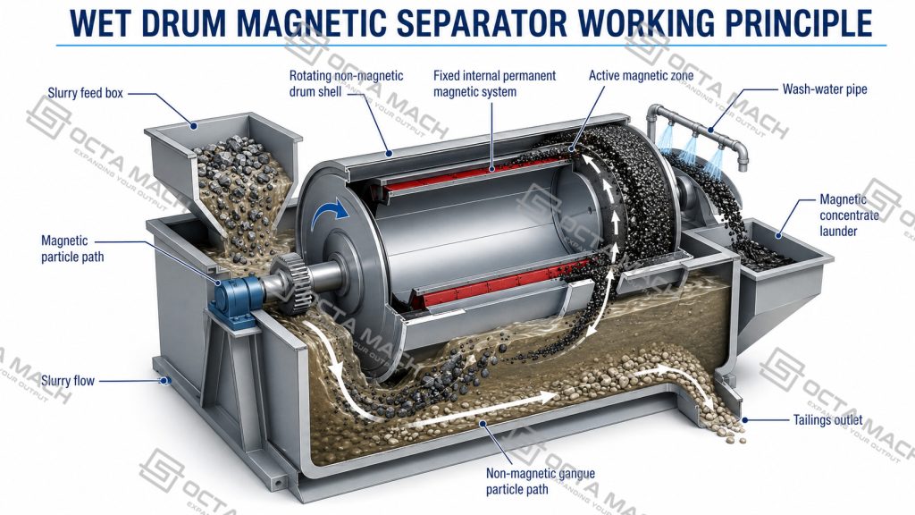
The main separation sequence is:
- Feed distribution — classified slurry enters the feed box at a controlled solids concentration.
- Particle presentation — particles move through the tank and enter the effective magnetic zone.
- Magnetic capture — magnetite and other strongly magnetic particles are attracted to the drum.
- Transport and cleaning — the rotating drum carries the captured material while water removes entrained gangue.
- Concentrate discharge — magnetic particles leave the field and fall into the concentrate launder.
- Tailings discharge — non-magnetic particles exit through the tank discharge.
Magnetic separation is therefore not controlled by magnet strength alone. Separation occurs when the magnetic force acting on a particle is sufficient to overcome competing forces such as gravity, slurry drag, particle collision and mechanical entrainment.
Wet vs Dry Magnetic Separator
The wet vs dry magnetic separator decision depends on feed moisture, particle size, process-water availability and the location of the separator in the beneficiation circuit.
| Item | Wet Magnetic Separator | Dry Magnetic Separator |
| Feed condition | Mineral slurry | Dry, free-flowing ore |
| Typical position | After grinding and classification | After crushing or before grinding |
| Suitable particle range | Fine and classified feed | Coarser or dried material |
| Main application | Magnetite concentration and cleaning | Pre-concentration and impurity removal |
| Main advantage | Better control of fine particles | No process-water requirement |
| Main limitation | Requires pumps and slurry handling | Moist or sticky feed reduces stability |
| Typical equipment | Wet drum magnetic separator | Dry drum, roll or belt separator |
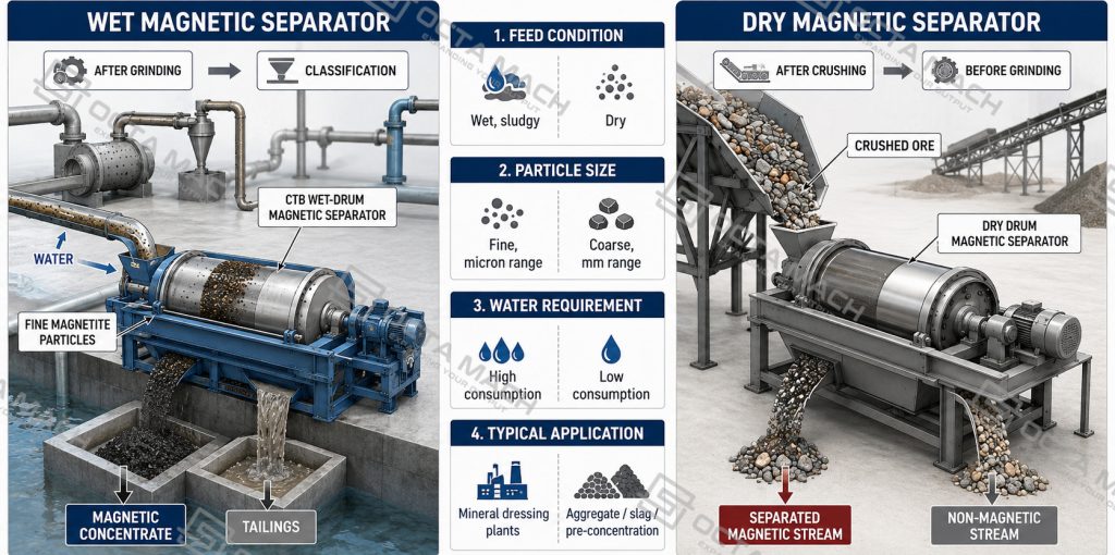
A mineral processing magnetic separator installed after grinding and classification normally handles wet feed because the valuable minerals must first be liberated from gangue. Dry separation is more suitable where water is unavailable, where the ore can be upgraded before grinding or where the objective is removal of metallic contamination rather than fine mineral concentration.
Iron Ore and Magnetite Applications
An iron ore magnetic separator is especially effective for magnetite because magnetite responds strongly to low-intensity magnetic fields.
A typical magnetite beneficiation circuit includes:
Crushing → Grinding → Classification → Rougher Magnetic Separation → Cleaning → Thickening → Filtration.
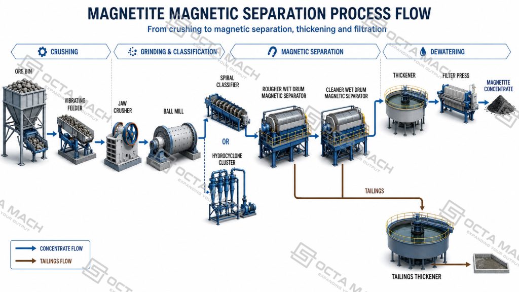
Magnetite is treated mainly by magnetic separation, while hematite may require strong magnetic separation followed by reverse flotation. Manganese ore may combine washing, screening, gravity separation and strong magnetic separation.
| Mineral or Feed | Magnetic Response | Typical Process Direction |
| Magnetite | Strong | Low-intensity wet-drum separation |
| Hematite | Weak | High-intensity separation or magnetic separation plus reverse flotation |
| Limonite | Weak and variable | High-intensity or high-gradient separation |
| Manganese ore | Variable | Strong magnetic separation or combined beneficiation |
| Ilmenite | Moderate | High-intensity wet or dry separation |
| Quartz with iron impurities | Non-magnetic host | Magnetic impurity removal |
A standard CTB magnetite magnetic separator should not be selected directly for weakly magnetic hematite or manganese ore without mineralogical analysis and beneficiation testwork.
Main Components
The magnetic separator is built around a rotating drum and a fixed internal magnetic system. Each component contributes to stable slurry handling, magnetic capture and continuous product discharge.
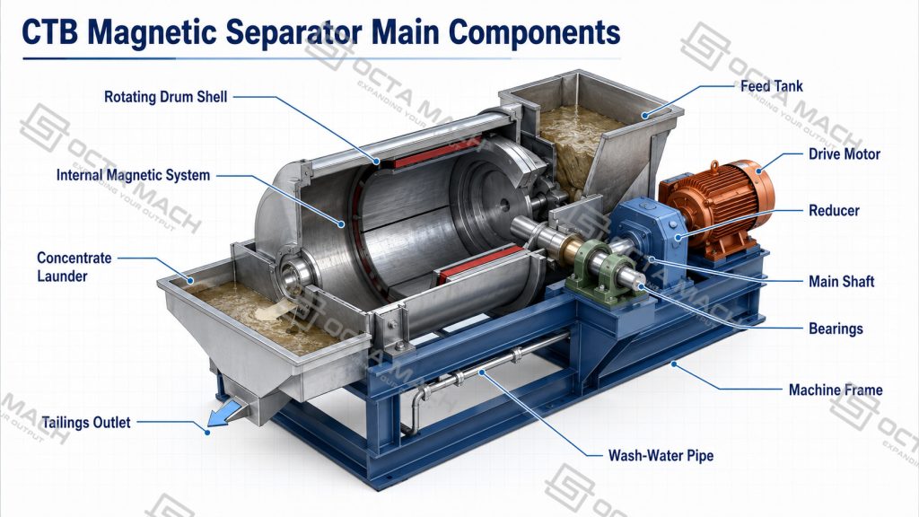
Rotating Drum Shell
Carries captured magnetic particles through the active separation zone and toward the concentrate discharge.
Internal Magnetic System
Generates the magnetic field required to attract and retain magnetically responsive particles.
Feed Tank
Distributes mineral slurry evenly across the effective working width of the drum.
Concentrate Launder
Collects magnetic material released from the drum after it leaves the active magnetic zone.
Tailings Outlet
Discharges non-magnetic and weakly magnetic particles remaining in the slurry.
Drive Motor and Reducer
Provide controlled drum rotation at the speed specified for the selected model.
Main Shaft and Bearings
Support the rotating assembly, maintain alignment and ensure smooth operation.
Machine Frame
Supports the drum, tank, drive and discharge assemblies as one integrated structure.
Wash-Water System
Removes entrained gangue from the magnetic product where additional concentrate cleaning is required.
Product Supply and Technical Support
Octa Mach supplies CTB wet-drum magnetic separators together with matched feeders, crushers, ball mills, classifiers, thickeners and filtration equipment. Technical support covers model selection, process-flow matching, installation guidance, commissioning assistance, spare-parts supply and after-sales service, allowing the magnetic separator to be integrated into a complete mineral-processing circuit rather than supplied as an isolated machine.
FAQ
Q: What is the difference between magnetic separation and a magnetic separator?
A: Magnetic separation is the beneficiation process that uses differences in mineral magnetic susceptibility. A magnetic separator is the machine that produces the controlled magnetic field and separates the magnetic and non-magnetic product streams.
Q: Can one magnetic separator process both magnetite and hematite?
A: Not necessarily. Magnetite normally responds to low-intensity wet-drum separation, while hematite usually requires stronger magnetic fields, high-gradient equipment or a combined magnetic separation and reverse-flotation process.
Q: How should magnetic separator capacity be selected?
A: Start with dry-solids throughput and slurry flow, then check feed size, pulp density, liberation, drum width, required cleaning stages and the magnetic response of the ore. Nominal capacity alone is not sufficient.
Q: Does higher magnetic field intensity always improve recovery?
A: A higher field may capture finer or weaker magnetic particles, but it can also increase recovery of locked particles and entrained gangue. Field intensity must be balanced against concentrate-grade requirements.
Q: Why are several magnetic separators installed in series?
A: Multiple units may perform roughing, cleaning and scavenging duties. This allows the plant to recover magnetic minerals while controlling gangue entrainment and final concentrate quality.