Different flotation machine models are not interchangeable tanks with different capacities. The model series identifies how the machine introduces air, circulates slurry and transfers pulp between cells, while the model number commonly indicates nominal effective cell volume. Even two machines with the same 8 m³ volume can require different impeller sizes, drive power, air-supply systems and plant layouts.
For example, the catalogue lists both the KYF-8 and SF-8 as 8 m³ flotation cells. The KYF-8 uses a 15 kW main drive, a 630 mm impeller and an external low-pressure air supply. The SF-8 uses a 760 mm impeller, operates at 191 r/min and lists 30/1.5 kW for its drive and scraper system. The nominal volume is the same, but their aeration method and hydrodynamic duties are different.
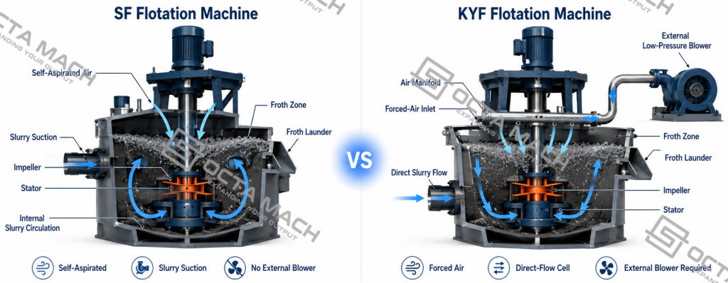
Mechanical flotation cells use a rotor–stator or impeller system to keep particles suspended, disperse air and promote particle–bubble contact. Air may be drawn naturally into the cell by the rotating mechanism or supplied under pressure by an external blower. These two approaches create different relationships between impeller speed, air rate, slurry circulation and process control.
Model Numbers and Machine Design
In the supplied catalogue, the number following SF or KYF corresponds approximately to the effective volume of one cell:
- SF-0.7: 0.7 m³
- SF-4: 4 m³
- SF-20: 20 m³
- KYF-1: 1 m³
- KYF-8: 8 m³
- KYF-38: 38 m³
This convention is useful for preliminary comparison, but the number alone does not define:
- Slurry-handling capacity
- Air-induction method
- Required blower pressure
- Impeller diameter and speed
- Slurry-suction capability
- Motor and auxiliary power
- Bank arrangement
- Mineral recovery or concentrate grade
A larger model provides more residence volume, but it cannot correct unsuitable feed preparation, poor mineral liberation, unstable air dispersion or an incorrect reagent scheme.
Main Flotation Machine Families
The most important difference between flotation machine models is their method of air induction and slurry transport.
| Model family | Aeration method | Slurry-suction capability | Typical circuit role | Main selection consideration |
|---|---|---|---|---|
| SF | Self-aspirated mechanical agitation | Yes | Independent cells, suction positions, roughing or scavenging | Flexible layout without a separate air blower |
| KYF | Forced air from an external blower | No | Direct-flow cells in medium and large flotation banks | Independent airflow control and larger-volume configurations |
| XCF | Forced-air mechanical agitation | Yes | Suction cell installed at the head of a KYF bank | Transfers slurry into downstream KYF cells |
| JJF | Self-air-induction mechanical agitation | No | Direct-flow cell, often combined with a suction-type cell | Stable circulation with separate slurry-transfer arrangement |
| BF | Self-aspirated, with suction and non-suction configurations | Model-dependent | Roughing, cleaning or heavier-mineral duties | Strong circulation and configuration flexibility |
SF cells combine mechanical agitation, air suction and slurry suction. KYF cells use externally supplied low-pressure air and generally require an appropriate feed arrangement because they do not independently lift slurry. XCF cells add slurry-suction capability and are commonly installed at the head of a KYF bank. JJF cells induce air but do not normally provide independent slurry suction.
The table should be treated as a functional comparison rather than a universal ranking. Actual rotor geometry, stator design and control arrangement vary by manufacturer.
KYF Flotation Machine Parameters
The KYF range in the supplied catalogue extends from 1 m³ to 38 m³ per cell. The listed capacity is expressed in m³/min of slurry, not tonnes per hour of dry ore.
| Model | Tank size, L × W × H (mm) | Effective volume (m³) | Catalogue slurry capacity (m³/min) | Main motor (kW) | Impeller diameter (mm) | Scraper motor (kW) |
|---|---|---|---|---|---|---|
| KYF-1 | 1000 × 1000 × 1100 | 1 | 0.2–1 | 4.0 | 340 | 1.1 |
| KYF-2 | 1300 × 1300 × 1250 | 2 | 0.4–2 | 5.5 | 410 | 1.1 |
| KYF-3 | 1600 × 1600 × 1400 | 3 | 0.6–3 | 7.5 | 480 | 1.5 |
| KYF-4 | 1800 × 1800 × 1500 | 4 | 1.2–4 | 11.0 | 550 | 1.5 |
| KYF-8 | 2200 × 2200 × 1950 | 8 | 3–8 | 15.0 | 630 | 1.5 |
| KYF-16 | 2800 × 2800 × 2400 | 16 | 4–16 | 30.0 | 740 | 1.5 |
| KYF-24 | 3100 × 3100 × 2900 | 24 | 4–24 | 30.0 | 800 | 1.5 |
| KYF-38 | 3600 × 3600 × 3400 | 38 | 10–38 | 37.0 | 880 | 1.5 |
However, the entry shown for KYF-24 appears inconsistent with the adjacent models and should be reconfirmed against the final manufacturer datasheet before publication, quotation or blower selection. It has therefore not been reproduced in this table.
SF Flotation Machine Parameters
The supplied SF range covers effective cell volumes from 0.7 m³ to 20 m³.
| Model | Effective volume (m³) | Tank size, L × W × H (mm) | Impeller diameter (mm) | Impeller speed (r/min) | Catalogue slurry capacity (m³/min) | Catalogue motor entry, main/scraper (kW) | Air intake (m³/min) |
|---|---|---|---|---|---|---|---|
| SF-0.7 | 0.7 | 820 × 900 × 950 | 350 | 400 | 0.3–0.9 | 3/1.1 | 0.8–1.0 |
| SF-1.2 | 1.2 | 1100 × 1100 × 1100 | 450 | 312 | 0.6–1.2 | 5.5/1.1 | 1.0–1.2 |
| SF-2.8 | 2.8 | 1700 × 1600 × 1150 | 550 | 268 | 1.5–3.5 | 11/1.5 | 1.0–1.2 |
| SF-4 | 4.0 | 1850 × 2050 × 1200 | 650 | 220 | 2–4.0 | 15/1.5 | 1.0–1.2 |
| SF-8 | 8.0 | 2200 × 2900 × 1400 | 760 | 191 | 4–8.0 | 30/1.5 | 0.9–1.0 |
| SF-10 | 10.0 | 2200 × 2900 × 1700 | 760 | 191 | 5–10.0 | 30/1.5 | 0.9–1.0 |
| SF-16 | 16.0 | 2850 × 3800 × 1700 | 760 | 191 | 5–16.0 | 30 × 2/1.5 | 0.9–1.0 |
| SF-20 | 20.0 | 2850 × 3800 × 2000 | 760 | 191 | 5–20.0 | 30 × 2/1.5 | 0.9–1.0 |
These figures are suitable for preliminary model comparison. They are not unconditional guarantees of dry-ore throughput or metallurgical recovery.
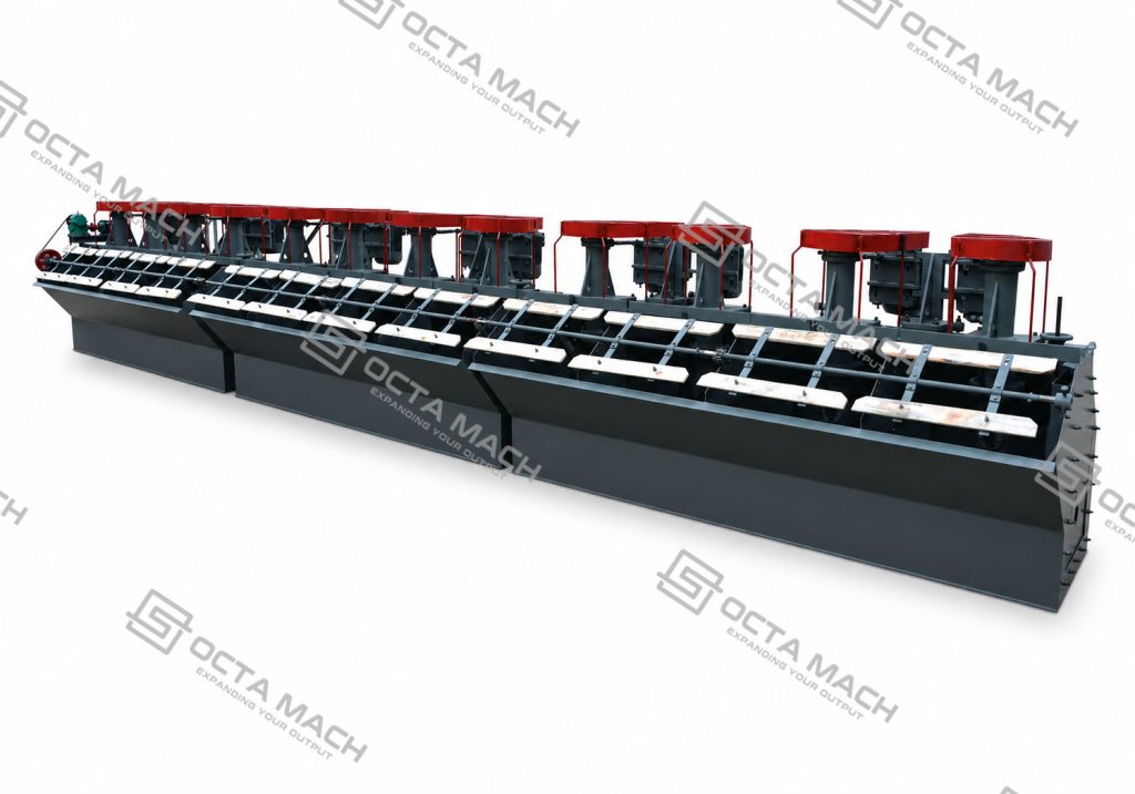
SF and KYF Flotation Machines Compared
Air Supply
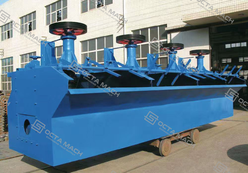
An SF flotation machine uses the negative pressure generated by the rotating impeller to draw air into the pulp. As a result, air intake is linked to impeller condition, rotational speed, pulp density and slurry rheology.
A KYF flotation machine receives low-pressure air from an external blower. Its impeller primarily suspends solids, circulates slurry and disperses the supplied air. The air rate can therefore be adjusted more independently from the mechanical mixing duty.
Forced-air cells can provide a wider operating-control window, but they also require blowers, valves, piping and airflow instrumentation. Self-aspirated cells simplify the auxiliary-air system, although their aeration and mixing duties are more closely coupled.
Slurry Transfer
Each SF cell can perform air suction, slurry suction and flotation. This allows it to operate as a suction cell or as part of a horizontally arranged bank without relying on a dedicated suction-type head cell.
A standard KYF cell does not provide the same slurry-suction function. A KYF bank may therefore use:
- A suitable elevation difference
- A feed or transfer pump
- An XCF suction cell at the beginning of the bank
- A carefully designed gravity-flow arrangement
This difference affects plant elevation, pump count, piping, intermediate return and maintenance access—not just the flotation cell itself.
Hydrodynamics
The SF mechanism generates strong internal circulation while drawing air and pulp through the impeller zone. This can support solids suspension in compact or flexible circuits, but the available air rate changes with mechanical and slurry conditions.
The KYF mechanism separates air delivery from much of the suspension duty. This can make airflow easier to regulate across a large rougher or scavenger bank. Nevertheless, excessive air, excessive impeller speed or poor pulp-level control can still create unstable froth, entrainment or sanding.
Flotation performance depends on repeated circulation of pulp through the active impeller zone, where particle–bubble collision and attachment are most likely to occur. Tank volume alone does not describe this contacting opportunity.
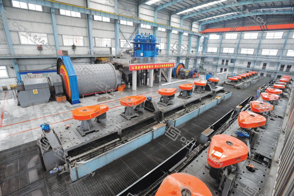
KYF-8 vs SF-8
Comparing two models with the same nominal effective volume shows why cell size alone is not enough.
| Item | KYF-8 | SF-8 |
|---|---|---|
| Effective volume | 8 m³ | 8 m³ |
| Tank size | 2200 × 2200 × 1950 mm | 2200 × 2900 × 1400 mm |
| Catalogue slurry capacity | 3–8 m³/min | 4–8 m³/min |
| Main-drive entry | 15 kW | 30 kW |
| Impeller diameter | 630 mm | 760 mm |
| Impeller speed | Not stated in catalogue | 191 r/min |
| Air system | External low-pressure blower | Self-aspirated |
| Slurry suction | No standard self-suction | Yes |
| Typical layout implication | Requires feed-transfer planning or XCF pairing | Can form a more self-contained flotation bank |
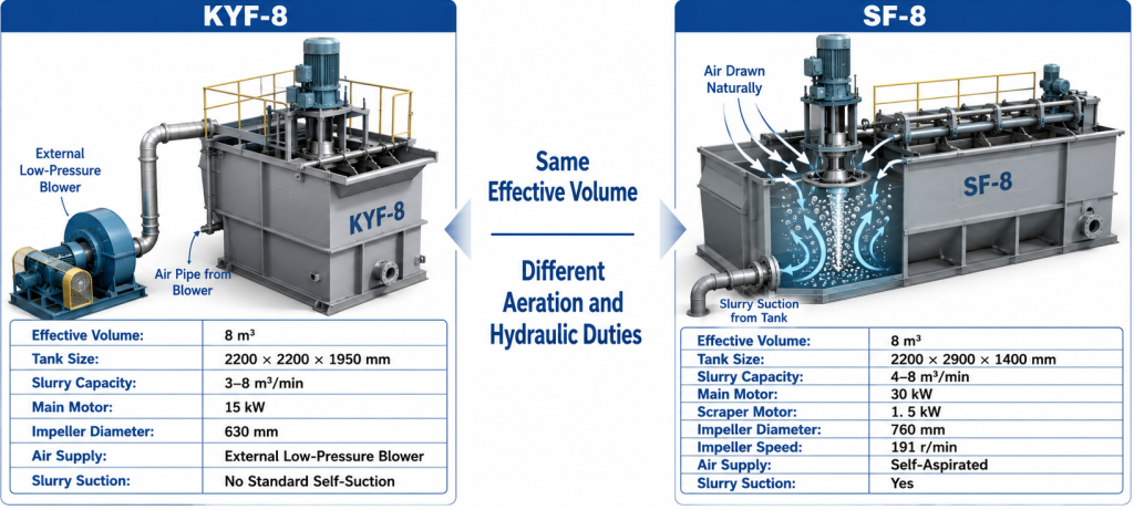
The comparison does not mean that the lower-motor model will always consume less total plant power. A KYF installation must also account for blower power, airflow-control equipment and any required slurry pumps. An SF installation may avoid an external blower but uses its impeller to perform suspension, circulation and air induction simultaneously.
Flotation Stages and Model Selection
A flotation circuit normally includes several process duties, and the best model for one duty may not be the best for another.
| Circuit stage | Main objective | Important machine characteristics | Typical model tendency |
|---|---|---|---|
| Roughing | Recover as much liberated valuable mineral as practical | High slurry capacity, stable suspension, adequate air rate and rapid froth transport | Larger KYF or other forced-air cells; SF in smaller or flexible circuits |
| Cleaning | Increase concentrate grade and reject entrained gangue | Stable froth depth, accurate level control, controlled agitation and low entrainment | Forced-air or direct-flow cells with good froth control |
| Scavenging | Recover slow-floating or remaining valuable particles | Sufficient residence time, robust circulation and tolerance of variable feed | SF, BF or forced-air cells selected according to particle size and density |
| Recleaning | Produce final concentrate quality | Gentle pulp conditions, selective froth and low mass pull | Smaller cells or finely controlled direct-flow cells |
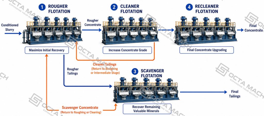
Rougher cells are not automatically “high-power machines,” and cleaner cells are not automatically “small machines.” The correct configuration depends on flotation kinetics, mass pull and the number of cells required to achieve the target residence-time distribution.
Flotation Cell Sizing
The catalogue capacity values are expressed in m³/min, which indicates a slurry-volume range. This is not the same as dry-solids throughput in tonnes per hour.
The preliminary sizing relationship is:
Required total effective volume
= slurry volumetric flow × required flotation residence time
The preliminary number of cells can then be estimated from:
Number of cells
= required total effective volume ÷ effective volume per cell
However, final sizing must also consider:
- Actual operating volume
- Froth volume
- Short-circuiting and mixing behavior
- Solids concentration
- Recirculating middlings
- Stage recovery
- Maintenance availability
- Number of cells required for process control
For example, a slurry flow of 4 m³/min does not automatically mean that one KYF-4 or SF-4 cell is sufficient. If the ore requires several minutes of flotation residence time, multiple cells or a larger total bank volume will be necessary.
Using Different Flotation Models Together
One flotation circuit does not always need one model family from beginning to end.
XCF and KYF Combination
A common arrangement uses an XCF cell at the head of a group and KYF cells downstream.
The XCF cell provides slurry suction and transfers pulp into the bank. The KYF cells then operate as direct-flow forced-air cells. This arrangement can reduce the need for a separate transfer pump between certain cell groups, provided that the elevation, hydraulic gradient and middlings-return system are correctly designed.
SF and JJF Combination
An SF cell can serve as the slurry-suction cell, followed by JJF direct-flow cells. Because JJF induces air but does not normally suck slurry, the SF head cell provides the hydraulic function needed for a horizontal bank arrangement.
Single-Series Flotation Banks
A complete SF bank may be suitable where self-suction, compact auxiliary systems and flexible process routing are priorities.
A complete KYF bank may be suitable where slurry transfer is handled separately and independent air control is required across a larger installation.
The combination should be selected from the whole flowsheet. Mixing model families only because they have different prices or nominal volumes can create incompatible elevations, unstable feed transfer or unnecessary pumping.
Ore type alone does not determine the flotation machine model; mineralogy, particle size, slurry density, flotation kinetics and circuit duty must be reviewed together.
Flotation Machine Selection Checklist
Before comparing flotation machine models, confirm the following process inputs:
| Selection input | Information required |
|---|---|
| Mineralogy | Valuable minerals, gangue minerals and oxidation state |
| Liberation | Size at which valuable minerals become sufficiently liberated |
| Feed particle size | Full particle-size distribution, including fines and coarse fraction |
| Slurry conditions | Flow rate, solids concentration, density, temperature and viscosity |
| Process duty | Roughing, cleaning, scavenging or recleaning |
| Flotation kinetics | Fast- and slow-floating fractions from testwork |
| Air requirement | Required airflow range, pressure and control method |
| Residence time | Required total effective volume and number of cells |
| Plant layout | Available elevation, pumps, blower space and maintenance access |
| Froth handling | Froth depth, launder loading, mass pull and level control |
| Wear conditions | Abrasiveness, solids loading and expected rotor–stator wear |
| Utilities | Voltage, frequency, installed power and air supply |
| Test data | Laboratory batch tests, locked-cycle tests or pilot results |
FAQ
Q: Is a KYF flotation machine better than an SF flotation machine?
A: Neither model is universally better. KYF provides externally controlled forced air and is available in larger cell volumes, while SF provides self-air and self-slurry suction. The better choice depends on circuit layout, air control, slurry transfer, process stage and ore response.
Q: Is a KYF flotation machine better than an SF flotation machine?
A: Neither model is universally better. KYF provides externally controlled forced air and is available in larger cell volumes, while SF provides self-air and self-slurry suction. The better choice depends on circuit layout, air control, slurry transfer, process stage and ore response.
Q: Can the catalogue capacity in m³/min be converted directly into t/h?
A: No. The published figure represents slurry volume. Converting it into dry-solids throughput requires slurry density, solids concentration and reliable process-flow data.
Q: Which flotation machine is suitable for copper, gold or lead-zinc ore?
A: The ore name is insufficient for final selection. Copper ore flotation, gold-bearing sulfide flotation and lead-zinc flotation can all use SF, KYF or combined banks, depending on particle size, density, flotation kinetics, rougher or cleaner duty, and the required hydraulic arrangement.
Q: Does a larger flotation-cell volume guarantee higher recovery?
A: No. Larger volume increases available residence capacity, but recovery also depends on mineral liberation, flotation kinetics, particle suspension, air dispersion, reagent chemistry and froth recovery.