
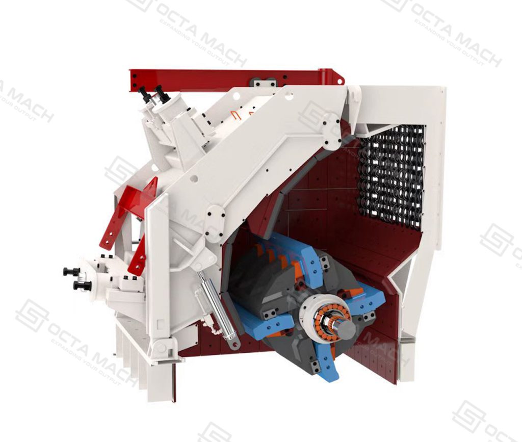
Impact Crusher Blow Bars strike incoming rock as the rotor rotates, accelerating the material toward the impact aprons inside a Horizontal Shaft Impact Crusher (HSI). Through repeated impacts, larger rocks are reduced into smaller particles, while the blow bars withstand continuous impact and abrasive wear. As the working edges gradually wear down, their profile changes, making material selection and replacement condition important to maintaining stable crusher operation.
Replacing worn blow bars requires more than matching the original length and width. The alloy composition, impact resistance, mounting profile and unit weight must suit both the feed material and the rotor assembly. A bar designed for highly abrasive limestone may not perform equally well when processing reinforced concrete containing steel.
Octa Mach supplies Impact Crusher Blow Bars as part of its crusher wear parts range, with replacement specifications matched to the crusher model, rotor design and intended application.
Impact Crusher Blow Bar Specifications
Impact crusher blow bars are manufactured in different profiles and dimensions to match specific rotor assemblies. The overall length, width, height, mounting surfaces and weight determine whether a replacement bar can be correctly installed and operated within the crushing chamber.
The following specifications are used to identify and confirm a suitable replacement:
| Specification | Description |
|---|---|
| Material Type | Manganese steel, martensitic steel, high chrome cast iron or ceramic-insert composite, subject to availability |
| Material Grade | Confirmed according to the specified alloy and material requirements |
| Length × Width × Height | Manufactured according to the original part dimensions or approved drawing |
| Unit Weight | Matched to the specified rotor arrangement |
| Rotor Compatibility | Confirmed against crusher make, model and rotor configuration |
| Mounting Configuration | Determined by the bar profile, contact surfaces and retaining system |
| Reversible Design | Available only for profiles designed and approved for turning |
| Application | Limestone, concrete recycling, asphalt and other suitable impact-crushing duties |
Blow bars may look similar in shape, but small differences in mounting surfaces, retaining features and unit weight can affect how they fit and perform on the rotor. Checking these details against the original crusher configuration helps avoid unnecessary fitting problems and ensures that the replacement is suitable for the intended application.
When enquiring about replacement blow bars, you can start with the crusher model and original part number. If available, a technical drawing or a sample of the existing bar will make it easier to confirm the dimensions and mounting details. Information about the feed material, maximum feed size and current wear pattern is also helpful, as it gives a clearer picture of the working conditions and helps identify a suitable material.
Blow Bar Structure and Working Function
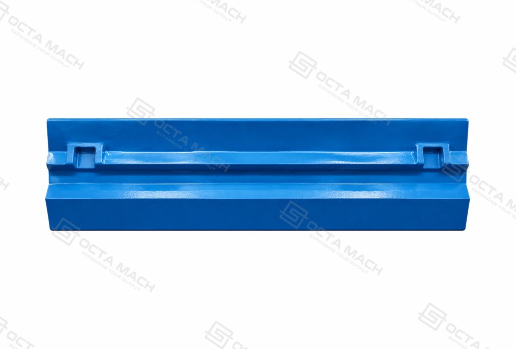
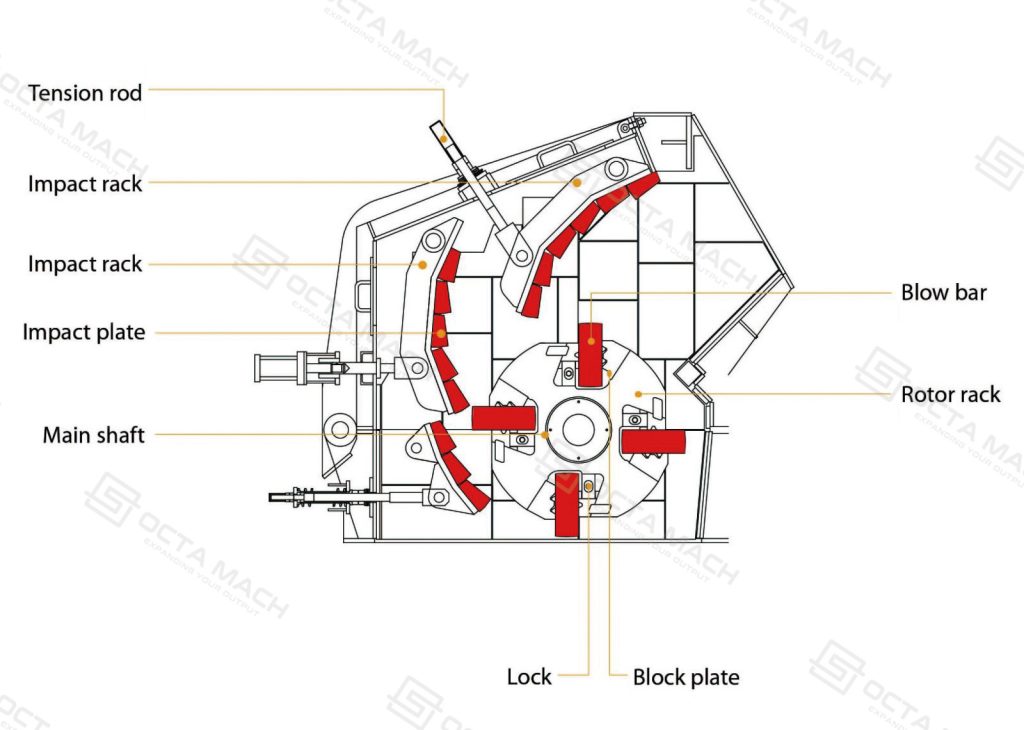
Inside an HSI crusher, blow bars are fitted into designated positions on the rotating rotor. They form the main impact surfaces that strike incoming material and accelerate it toward the impact aprons. The retaining arrangement keeps each bar seated against the rotor while it operates under high rotational speed and repeated impact loading.
The main components involved in blow bar installation and operation include:
| Component | Function |
|---|---|
| Blow Bar | Strikes incoming material and transfers impact energy into the crushing process |
| Rotor | Supports and rotates the blow bars at the required operating speed |
| Locking Wedges | Secure the blow bars against their designated contact surfaces, where this retaining arrangement is used |
| Mounting Surface | Establishes the seating position and load-transfer interface between the bar and rotor |
| Impact Aprons | Receive projected material and create additional impact and reduction inside the chamber |
During operation, the rotor drives the blow bars through the feed material. The initial impact breaks larger particles and accelerates the fragments toward the impact aprons. Material rebounds toward the rotor and receives further impact until it reaches a size that can pass through the discharge area.
The blow bars, rotor and impact aprons therefore work as one mechanical system. A poorly seated bar, damaged clamping surface or incorrect retaining arrangement can affect the security of the installation. A secure fit and properly engaged retaining components help keep the blow bar firmly in place as the rotor runs.
Blow Bar Materials and Selection
Material selection has a direct effect on blow bar service life and replacement frequency. The main consideration is the relationship between abrasion resistance and impact resistance. A material that performs well against abrasive wear may be unsuitable when the crusher receives large feed or uncrushable metal.
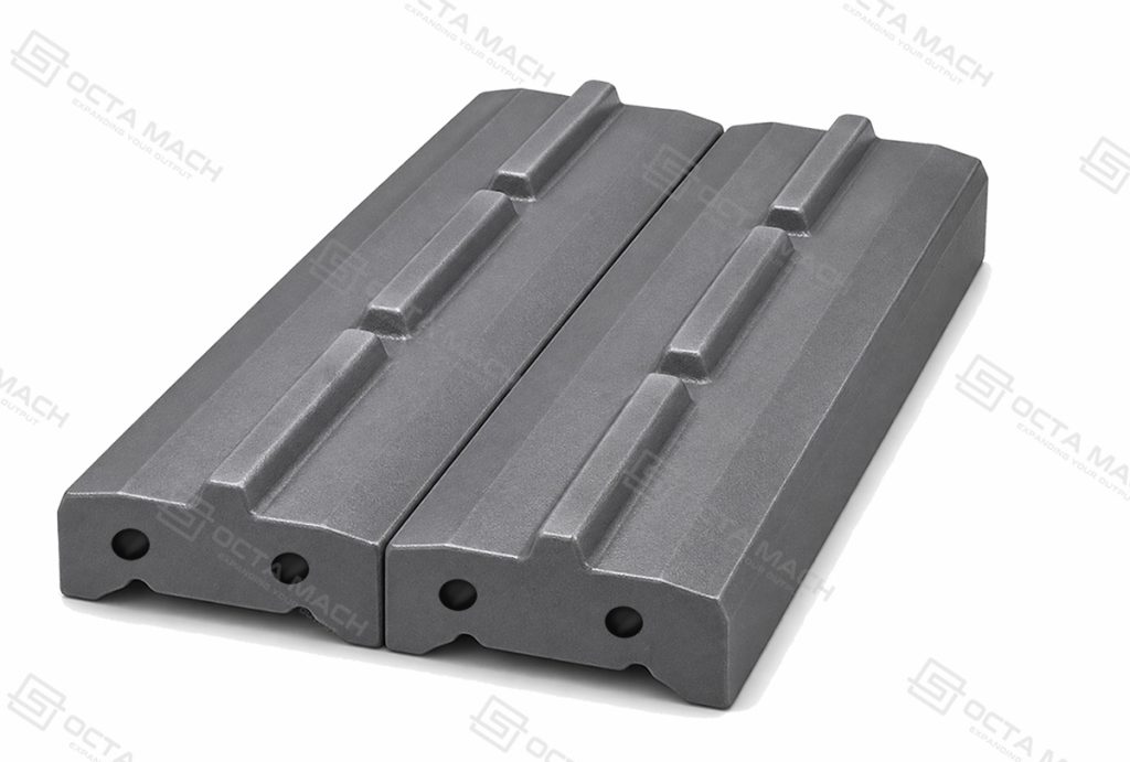
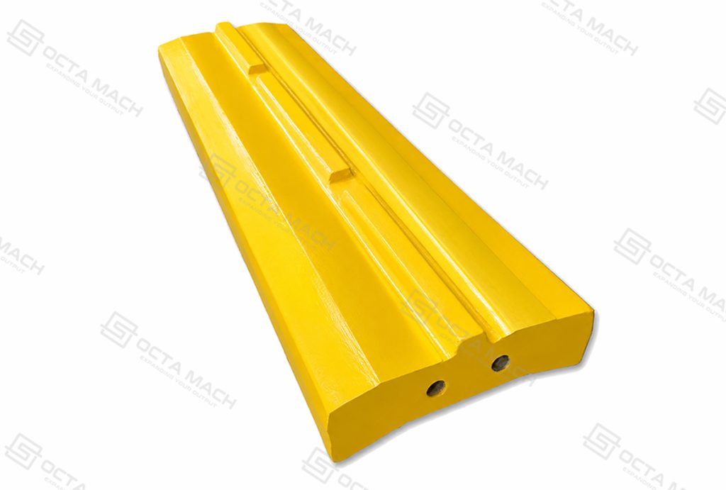
Common HSI blow bar material families include manganese steel, martensitic steel, high chrome cast iron and ceramic-insert composites. Each has a different operating range.
Manganese Steel Blow Bars
Manganese steel is selected primarily for applications with substantial impact loading. Its work-hardening characteristics allow the surface to harden under repeated impact, while the material retains relatively high toughness.
It is commonly considered for primary impact-crushing duties, larger feed and applications where occasional tramp metal may enter the crushing chamber. However, sufficient impact is needed for work hardening to contribute effectively. In highly abrasive conditions with insufficient impact loading, manganese bars may wear more quickly than other alloy options.
Martensitic Steel Blow Bars
Martensitic steel combines hardness with impact resistance, making it a practical option for applications where manganese steel wears too quickly but high chrome material would carry excessive breakage risk.
Typical applications include quarry rock, limestone, building rubble and concrete recycling. The actual performance depends on feed size, alloy composition, heat treatment and abrasive content.
For mixed demolition material, the presence of reinforcement steel and other uncrushable objects must be considered before selecting the grade.
High Chrome Cast Iron Blow Bars
High chrome cast iron offers high hardness and strong resistance to abrasive wear. It is generally considered for secondary or tertiary crushing, where the feed size is controlled and the material entering the chamber has a relatively consistent composition.
Its main limitation is lower impact tolerance compared with tougher steel alloys. Large feed, tramp iron and sudden impact overloads can cause cracking or breakage. High chrome bars are therefore better suited to controlled crushing conditions than applications involving frequent uncrushable material.
Ceramic Insert Blow Bars
Ceramic insert blow bars combine a metallic matrix with ceramic reinforcement in selected wear areas. The matrix may be based on martensitic steel or high chrome cast iron, depending on the product design.
The ceramic inserts increase resistance to abrasive wear in suitable applications. They are often considered for secondary crushing, natural stone processing and selected recycling duties where feed size and metal contamination are controlled.
Ceramic reinforcement does not eliminate the need for impact resistance. A bar with ceramic inserts can still fail if exposed to excessive feed size, tramp metal or an unsuitable impact load.
Material Selection Comparison
| Material | Wear Resistance | Impact Resistance | Suitable Operating Conditions |
|---|---|---|---|
| Manganese Steel | Depends on work-hardening conditions and feed abrasiveness | High | High-impact duties and larger feed |
| Martensitic Steel | Moderate to high | Moderate to high | Quarry rock, limestone and mixed recycling feed |
| High Chrome Cast Iron | High | Relatively low | Controlled secondary and fine crushing |
| Martensitic Ceramic | High | Depends on the martensitic matrix and insert design | Abrasive feed with controlled impact conditions |
| Chrome Ceramic | Very high in suitable applications | Depends on the matrix and insert design | Highly abrasive, pre-crushed and controlled feed |
Hardness and impact resistance both influence how a blow bar performs in service, but they are not the same property. Higher hardness can help the material resist abrasive wear, while excessive hardness without sufficient toughness may increase the risk of cracking or breakage under heavy impact.
For example, concrete recycling often involves reinforcement steel and irregular feed sizes. In these conditions, a tougher martensitic or manganese-based alloy may be more suitable, depending on the impact load and feed characteristics. By comparison, clean, pre-crushed abrasive stone may be better suited to high chrome or ceramic-reinforced materials, where resistance to material loss is a greater priority.
In practice, the choice comes down to what the blow bars are expected to handle. Feed size, material abrasiveness, impact load and rotor configuration all affect how the bars wear during operation. Looking at these conditions together gives a much clearer basis for choosing an alloy than comparing hardness values alone.
Blow Bar Design and Rotor Compatibility
A replacement blow bar must match the mechanical interface of the rotor. Its working profile, mounting surface, clamping arrangement and overall weight determine how it sits inside the rotor and transfers impact and centrifugal loads during operation.
Several design details require confirmation before replacement:
Blow Bar Profile: The shape and working edge determine the contact geometry with incoming material. A different profile may change the impact surface and material trajectory inside the crushing chamber.
Mounting Surface: The contact area must match the rotor seat. Poor contact can concentrate loads on a smaller area and increase the risk of local damage.
Locking Structure: The bar must work with the original retaining system. Locking wedges, clamping surfaces, holes or other locating features must correspond to the rotor design.
Overall Weight: The mass of each bar affects the rotating assembly. Opposing positions must follow the crusher manufacturer’s specified weight-matching requirements.
Reversible Design: Some blow bars have symmetrical profiles that permit turning to use the opposite working edge. This feature must be confirmed from the original design; not every blow bar can be reversed.
Rotor Balance and Matched Weight
Blow bar weight matching is an important part of rotor maintenance. A rotating assembly with unequal mass distribution can develop imbalance, increasing vibration and dynamic loads on the rotor, bearings and supporting structure.
When replacing bars, the required matching procedure should follow the equipment manufacturer’s instructions. This may involve checking the weights of opposing bars, confirming their installation positions and inspecting the retaining components before the rotor is returned to service.
The original rotor arrangement should also be maintained. Some designs use different bar positions or profiles within the same rotor, so visually similar parts should not be assumed to be interchangeable.
Blow Bar Manufacturing
The manufacturing quality of an impact crusher blow bar depends on alloy composition, casting quality, heat treatment and the accuracy of its mounting surfaces. These factors determine whether the finished part can withstand repeated impact loading and fit correctly into the rotor assembly.
For cast alloy blow bars, the production route generally includes:
Pattern and Mold Preparation → Melting and Alloy Control → Casting → Heat Treatment → Machining → Inspection
Each stage has a different quality objective.
Pattern and Mold Preparation
The blow bar pattern defines the shape of the working edge, overall profile and mounting features. During mould preparation, the dimensions and shape of the casting cavity must account for alloy shrinkage and any machining allowance required on the finished part.
The mounting surfaces and contact areas deserve particular attention because they determine how the blow bar sits against the rotor. Changes in section thickness also need to be considered during mould design, as uneven cooling and solidification can contribute to shrinkage defects or internal porosity. These details affect both the dimensional accuracy and structural soundness of the finished casting.
Melting and Alloy Control
The chemical composition of a blow bar has a direct influence on its hardness, toughness and wear behavior. Different alloy families require different compositions, so manganese steel, martensitic steel and high chrome cast iron cannot be treated as interchangeable wear-resistant materials.
During melting, the charge materials and alloy additions must be controlled to meet the specified grade. Chemical composition analysis can be used to verify the melt before casting, while material identification helps maintain consistency between the specified grade and the finished product.
The alloy specification also needs to match the intended heat-treatment process. A change in chemical composition can affect the resulting microstructure and mechanical properties, even when the finished parts have similar external dimensions.
Casting and Heat Treatment
During casting, molten metal must fill the mould and solidify without defects that could compromise the blow bar under repeated impact. Shrinkage cavities, porosity, inclusions and cracks are among the defects that need attention, particularly around thicker sections and mounting features. Casting quality is especially important in areas exposed to repeated impact or mechanical loading.
Heat treatment then develops the properties required by the selected alloy. Manganese steel is generally solution-treated to retain its intended toughness and work-hardening characteristics. Martensitic steel requires a suitable hardening and tempering process to balance hardness with impact resistance, while high chrome cast iron requires heat treatment to develop the desired matrix hardness and wear performance.
These materials respond differently to thermal processing. The treatment cycle must therefore be established according to the actual alloy composition, casting section and required mechanical properties rather than applying one process to every blow bar.
Machining and Dimensional Inspection
After heat treatment, the mounting and clamping surfaces are machined where required to match the rotor assembly. Dimensional accuracy is particularly important at these contact areas, as poor fit can affect how the blow bar is seated and secured. Finished dimensions are checked against the approved drawing, including the key mounting features.
Final inspection focuses on the material properties, casting condition and dimensions that affect the blow bar’s performance and installation.
| Inspection Item | What Is Checked |
|---|---|
| Chemical Composition | Alloy content against the specified material grade |
| Hardness Testing | Hardness after heat treatment |
| Dimensional Inspection | Overall dimensions and critical mounting surfaces |
| Visual Inspection | Surface cracks and visible casting defects |
| Internal Quality Inspection | Internal casting condition, using additional testing where specified |
| Weight Inspection | Individual weight and matching of opposing rotor bars |
The inspection scope depends on the material grade, product drawing and order requirements. Where additional NDT is required, the method should be suitable for the material and casting geometry.For replacement orders, material identification, batch marking and inspection records can also be specified to help customers check the parts against their original requirements.
Blow Bar Wear and Replacement
Blow bars gradually lose material as they strike incoming rock and operate against abrasive particles. Their wear condition changes the working profile of the rotor and can affect the impact conditions inside the crushing chamber.Recognizing different wear patterns helps identify whether the problem comes from material selection, feed distribution, impact conditions or installation.
Common Blow Bar Wear Conditions
| Wear Condition | Physical Appearance | Possible Cause |
|---|---|---|
| Uniform Wear | Gradual material loss across the working area | Normal abrasive wear under relatively stable operating conditions |
| Uneven Wear | Different wear depths across the bar or between rotor positions | Uneven feed distribution, material flow or operating conditions |
| Edge Chipping | Localized damage or material loss along the impact edge | Excessive impact loading, unsuitable alloy or uncrushable material |
| Cracking and Breakage | Visible cracks or separation of part of the bar | Impact overload, tramp metal, casting defects or incorrect material selection |
| Excessive Wear | Remaining bar section approaches the equipment’s specified wear limit | Extended operation, unsuitable material or high feed abrasiveness |
Wear Limit and Reversible Design
Some impact crusher blow bars have symmetrical profiles that allow the bar to be turned after the first working edge has worn. This design makes use of the opposite edge and can extend the usable period of the component.
However, reversible use depends on the original bar geometry and rotor arrangement. The clamping surfaces, retaining features and contact areas must remain suitable after turning. A bar with an asymmetrical profile or structural damage should not be reversed simply to obtain additional operating time.
The wear limit is another important replacement consideration. Continuing to operate with an excessively worn bar can expose the rotor or retaining structure to increased damage risk. The allowable remaining section must be determined from the crusher manufacturer’s maintenance instructions or the approved wear-part drawing.
Replacement and Rotor Balance
When replacing blow bars, the condition of the rotor seats, locking wedges and retaining components should be checked at the same time. Damaged contact surfaces or worn locking components can prevent a new bar from seating correctly.
Replacement bars should also be checked for weight compatibility. The required matching tolerance and installation arrangement depend on the crusher design.
Before restarting the crusher, maintenance personnel should verify that:
- The replacement bars match the specified rotor positions.
- Contact and clamping surfaces are correctly seated.
- Locking wedges and retaining components are secured according to the equipment instructions.
- Opposing bar weights meet the manufacturer’s requirements.
- The rotor and surrounding components have been inspected for damage.
All replacement work must be performed with the crusher stopped, isolated from its energy sources and secured against unintended movement. The rotor must be mechanically secured before personnel work inside the crushing chamber.
Applications of Impact Crusher Blow Bars
Impact crusher blow bars are used in crushing operations where material reduction takes place through repeated impact. Their working conditions vary considerably according to rock characteristics, feed size, metal contamination and crushing stage.Selecting the appropriate alloy for each application helps manage wear consumption and reduce unexpected component failure.
Limestone Crushing
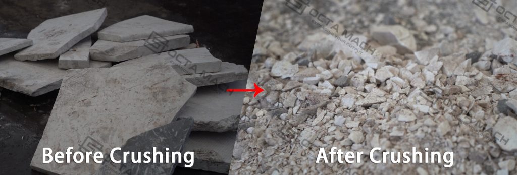
In limestone aggregate production, material commonly passes through primary crushing before entering a secondary impact crusher. The blow bars repeatedly strike the incoming limestone and project it toward the impact aprons, reducing particle size and helping produce cubical aggregate.
Limestone hardness and abrasiveness vary between deposits. Material containing higher silica content can cause more rapid abrasive wear, even when its overall compressive strength is relatively moderate.
Martensitic steel is one option for general impact-crushing conditions, while higher-wear-resistance materials may be considered when the feed is controlled and impact loading is suitable.
Concrete Recycling
Concrete recycling introduces a different combination of impact and wear conditions. The incoming material may contain concrete fragments, reinforcement steel, mortar, brick and other demolition debris.
The blow bars must withstand repeated impact from irregular concrete pieces. Reinforcement steel and other uncrushable objects can increase the risk of edge damage or bar breakage.
Martensitic steel is commonly considered for mixed concrete and demolition feed because it combines hardness with impact resistance. Manganese-based materials may also be evaluated where impact loading is particularly high.
Feed preparation, removal of oversized metal and magnetic separation should be considered as part of the recycling circuit.
Asphalt Recycling
Reclaimed asphalt pavement (RAP) is processed to reduce oversized material and prepare it for screening and reuse. Feed conditions can vary according to milling size, aggregate content, moisture and the presence of foreign objects.
Blow bar selection should account for the actual aggregate abrasiveness and the degree of feed-size control. Medium-chrome, martensitic or ceramic-reinforced materials may be considered depending on the operating conditions.
Consistent feeding and suitable impact-apron settings help maintain stable crushing conditions and avoid unnecessary wear.
Quarry and Aggregate Production
In quarry and aggregate plants, impact crushers are often installed after jaw crushers to reduce the primary product and improve particle shape.
The blow bars receive repeated impacts as material moves through the crushing chamber. Their wear rate depends on the feed-size distribution, rock abrasiveness, rotor speed and operating load.
For continuous aggregate production, replacement planning should consider the amount of material processed, the observed wear profile and the maintenance schedule. This allows wear-part changes to be coordinated with planned plant shutdowns.
Natural Stone Processing
Natural stone processing includes materials such as limestone, granite, basalt and other quarry rocks. Their mineral composition, hardness and abrasiveness can differ significantly.
For relatively low-abrasive stone, impact crushing can achieve a high reduction ratio and favorable aggregate shape. For quartz-rich or highly abrasive rock, however, blow bar consumption may become a major operating cost.
High chrome and ceramic-insert materials may be evaluated for controlled secondary crushing, but feed size and the possibility of tramp metal must be considered.
The choice between impact and compression crushing should also account for the expected wear cost. In highly abrasive applications, a cone crusher may offer a more economical operating arrangement.
Why Choose Octa Mach
Octa Mach’s product range covers crushing equipment and crusher wear parts, including impact crushers, blow bars, jaw plates, mantles, concaves and liners. This range covers several major components used in crushing plants, from complete machines to the wear parts required during routine operation.
Different crushing machines use different wear-part designs, and replacement requirements can vary between models. Octa Mach’s involvement in both crushing equipment and related parts gives the product range a practical connection to the equipment used in quarrying, mining and aggregate production.
Wear-part requirements may involve a single replacement component or several different parts for the same project. Octa Mach’s supply range accommodates both types of enquiries, with product specifications and quantities confirmed according to the equipment and order requirements.
FAQ
Q1:Are aftermarket impact crusher blow bars interchangeable with OEM parts?
A1:They can be used as replacements when the design is compatible with the original equipment. The rotor version, mounting profile, locking arrangement and critical dimensions must be checked. A matching crusher model alone does not guarantee a direct fit.
Q2:Can impact crusher blow bars be customized for different rotor designs?
A2:Non-standard requirements should be checked against the rotor drawing or original sample. Mounting surfaces, retaining features, profile and weight must all be verified before a replacement design is confirmed.
Q3:How can I identify when impact crusher blow bars need replacement?
A3:Check the remaining working section, impact edge, mounting surfaces and any signs of cracking or breakage. The replacement limit should follow the crusher manufacturer’s maintenance requirements rather than a universal wear measurement.
Q4:Can impact crusher blow bars be reversed to extend their service life?
A4:Only blow bars designed with a reversible or symmetrical profile should be turned. The opposite working edge, retaining surfaces and installation arrangement must remain suitable, and the manufacturer’s turning procedure should be followed.
Q5:What information is needed to order replacement impact crusher blow bars?
A5:Provide the crusher make and model, original part number, drawing or sample, overall dimensions, unit weight and rotor configuration. Feed material and operating conditions are also useful for material selection.