
Rotary Dryer is a large industrial machine used to reduce the moisture content of bulk materials inside a slightly inclined rotating cylinder. Internal lifting flights repeatedly raise and cascade the feed through a controlled hot-gas stream, increasing gas–solid contact so that moisture can evaporate continuously. This drying method is suitable for selected mineral concentrates, sand, slag, limestone, clay and coal before screening, grinding, storage, briquetting or further processing.
OctaMach supplies Rotary Drum Dryer models from Φ600 × 6000 mm to Φ3000 × 25000 mm, with published capacities of 0.5–55 t/h, drum inclinations of 3–5%, rotational speeds of 1.5–8 r/min and installed motor powers of 3–75 kW. Each dryer is selected according to the actual wet feed rate, inlet and target outlet moisture, particle-size distribution, bulk density, allowable material temperature and available heat source. Feed, hot-gas, exhaust, dust-collection and discharge interfaces can also be coordinated with the surrounding process equipment.
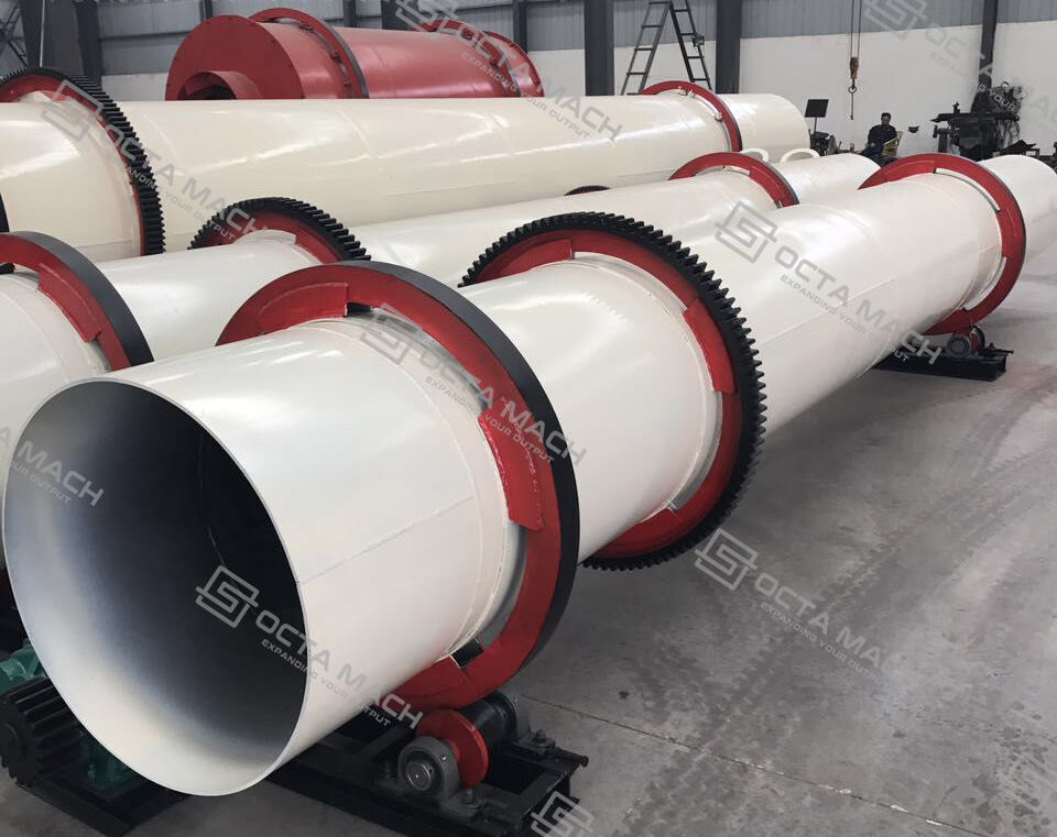
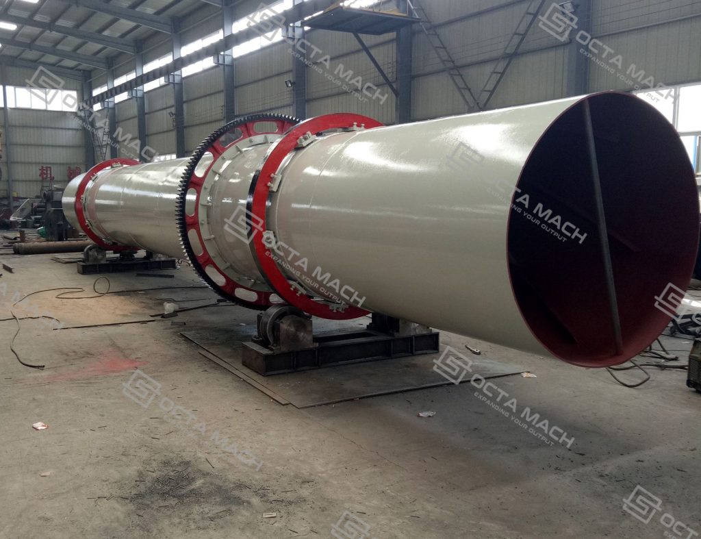
Rotary Dryer Specifications and Model Range
The following Rotary Dryer specifications are published for preliminary model comparison. The model designation represents the nominal drum diameter and drum length.
| Model | Drum Inclination (%) | Rotation Speed (r/min) | Maximum Inlet Gas Temperature (°C) | Motor Power (kW) | Published Capacity (t/h) | Machine Weight (t) |
|---|---|---|---|---|---|---|
| Φ600 × 6000 | 3–5 | 3–8 | ≤700 | 3 | 0.5–1.5 | 2.9 |
| Φ800 × 8000 | 3–5 | 3–8 | ≤700 | 4 | 0.8–2.0 | 3.5 |
| Φ800 × 10000 | 3–5 | 3–8 | ≤700 | 4 | 0.8–2.5 | 4.5 |
| Φ1000 × 10000 | 3–5 | 3–8 | ≤700 | 5.5 | 1.0–3.5 | 5.6 |
| Φ1200 × 12000 | 3–5 | 3–8 | ≤700 | 11 | 2–6 | 14.8 |
| Φ1500 × 12000 | 3–5 | 2–6 | ≤800 | 18.5 | 3.5–9 | 17.8 |
| Φ1800 × 18000 | 3–5 | 2–6 | ≤800 | 22 | 5–12 | 31 |
| Φ2000 × 18000 | 3–5 | 1.5–6 | ≤800 | 30 | 6–15 | 43 |
| Φ2200 × 18000 | 3–5 | 1.5–6 | ≤800 | 37 | 10–18 | 52 |
| Φ2400 × 20000 | 3–5 | 1.5–5 | ≤800 | 45 | 18–30 | 60 |
| Φ2800 × 20000 | 3–5 | 1.5–5 | ≤800 | 55 | 25–35 | 72 |
| Φ3000 × 20000 | 3–5 | 1.5–5 | ≤800 | 55 | 32–40 | 91 |
| Φ3000 × 25000 | 3–5 | 1.5–5 | ≤800 | 75 | 40–55 | 104.9 |
Published capacity is intended for preliminary model selection. It is not a guaranteed evaporation rate or dry-product output. Final Rotary Dryer capacity depends on the material, moisture basis, evaporation load, gas conditions, residence time, ambient conditions and complete system configuration. The published inlet-gas temperature is also not the same as the allowable product temperature.
Operating Principle
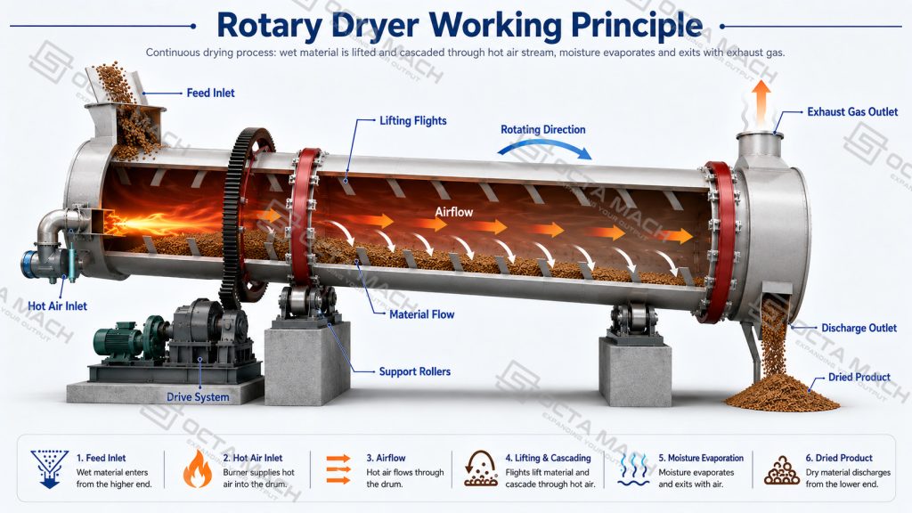
In the standard counter-current arrangement, wet material enters the elevated feed end of the Rotary Drum Dryer, while hot gas enters from the lower discharge end and flows in the opposite direction to the solids. The slightly inclined drum rotates slowly on riding rings and support rollers, driven by a motor, reducer and gear system. As the shell turns, internal lifting flights raise the material from the bottom of the drum and release it repeatedly through the hot-gas stream. This cascading action forms a distributed material curtain, exposes more particle surface to the drying gas and improves heat and mass transfer.
During this process, heat passes from the gas to the wet solids, causing moisture to evaporate. The induced-draft system carries the moisture-laden exhaust gas toward the gas outlet at the feed end, where entrained particles are separated by the specified dust-collection equipment. At the same time, the combined effects of drum inclination, gravity, rotation and flight geometry move the progressively dried material toward the lower discharge end for transfer to the downstream conveyor or processing equipment.
The drying sequence can be summarized as follows:
- Wet material enters the drum at a controlled feed rate.
- Internal flights lift and disperse the material through the hot-gas stream.
- Heat is transferred to the solids and moisture evaporates.
- Water vapor and entrained fines leave with the exhaust gas.
- The dried material advances toward the lower end of the drum.
- The product discharges continuously to the downstream handling system.
The lifting-flight system is a key process component rather than a simple internal support structure. Flight profile, spacing and arrangement determine how high the material is lifted, how evenly it is distributed across the drum and how effectively it contacts the drying gas. The flight configuration must therefore be matched to the material’s particle size, bulk density, abrasiveness, stickiness and resistance to degradation. Worn, damaged or poorly selected flights can create uneven material curtains, reduce heat transfer and produce unstable outlet moisture.
Main Components and Their Functions
An Industrial Rotary Dryer operates as a complete mechanical and thermal system. Stable performance depends on the drum, support system, gas circuit and material-handling interfaces working together.
| Component | Function | Main Operating Concern |
|---|---|---|
| Feed Chute | Introduces wet material into the elevated end | Blockage, surging and air leakage |
| Rotating Drum | Provides the drying and material-transport zone | Shell alignment, thermal expansion and internal buildup |
| Lifting Flights | Lift and cascade solids through the gas stream | Wear, bending, buildup and uneven material curtains |
| Riding Rings | Transfer drum load to the support rollers | Contact condition and drum alignment |
| Support Rollers | Carry the rotating drum | Lubrication, bearing temperature and uneven loading |
| Thrust Rollers | Limit excessive axial drum movement | Drum migration and concentrated axial load |
| Drive System | Rotates the shell at the required speed | Motor, reducer, coupling, pinion and gear condition |
| Inlet and Outlet Seals | Reduce false-air entry and dust leakage | Seal wear and uncontrolled cold-air ingress |
| Hot-Gas Generator | Provides thermal energy for moisture evaporation | Fuel condition, combustion control and gas temperature |
| Exhaust Fan | Maintains the required gas flow and system draft | Pressure loss, gas volume and site elevation |
| Dust Collector | Recovers entrained particles from the exhaust gas | Dust loading, gas temperature and condensation risk |
| Discharge Hood | Transfers dried solids to downstream equipment | Product temperature, sealing and blockage |
Controlled Material Exposure
The internal flights repeatedly lift the solids instead of allowing the feed to slide continuously along the bottom of the drum. This creates a larger gas–solid contact area and reduces dead zones inside the shell.
Adjustable Residence Time
Material residence time is influenced by the drum diameter and length, inclination, rotational speed, flight arrangement and feed characteristics. A longer drum does not automatically produce a better result; it must be matched to the required evaporation duty and material temperature limit.
Continuous Material Transfer
A properly sized feed system, stable drum speed and unobstructed discharge allow the Rotary Dryer Machine to operate continuously. Large changes in feed moisture or tonnage can disturb the thermal balance even when the mechanical equipment continues running.
Moisture Load and Drying Duty
Rotary dryer sizing is based on the required water evaporation rate, not wet feed tonnage alone. At the same wet feed rate, material with higher inlet moisture contains less dry solid and requires more heat to reach the specified outlet moisture. Dryer selection must therefore consider the wet feed rate, inlet and outlet moisture, bulk density, particle size, allowable product temperature, gas flow and residence time together.
When moisture content is stated on a wet basis, the preliminary material balance is calculated as follows:
| Calculation Item | Relationship |
|---|---|
| Dry Solids Rate | Wet Feed Rate × (1 − Inlet Moisture Fraction) |
| Final Product Rate | Dry Solids Rate ÷ (1 − Outlet Moisture Fraction) |
| Water Evaporation Rate | Wet Feed Rate − Final Product Rate |
| Equivalent Evaporation Relationship | Wet Feed Rate × (Inlet Moisture − Outlet Moisture) ÷ (1 − Outlet Moisture) |
These calculations assume that the dry-solid mass remains unchanged during drying. Final equipment sizing must also account for material heating, dust entrainment, exhaust-gas losses, shell heat loss, combustion conditions and operating variation.
Stable outlet moisture depends mainly on:
- Wet feed rate and inlet-moisture variation
- Hot-gas temperature and gas-flow rate
- Drum speed and material residence time
- Product discharge temperature
- Flight condition and internal material buildup
- Seal condition and false-air ingress
The published capacity of a Rotary Dryer should therefore be used only for preliminary model comparison. The final model must be confirmed against the actual evaporation duty and operating conditions.
Airflow and Heat Source
The standard Rotary Dryer uses direct gas–solid contact in a counter-current arrangement. Wet material enters from the elevated end, while hot gas enters from the discharge end and flows in the opposite direction. This arrangement maintains a strong drying force near the outlet, but the final material temperature must remain within the allowable limit.
A co-current arrangement feeds wet material and hot gas from the same end. The hottest gas contacts the wettest feed, while gas temperature decreases toward the discharge. This configuration may be considered when lower product-discharge temperature or gentler final drying is required.
Heat-source selection should be based on:
- Required evaporation and thermal duty
- Fuel availability and calorific value
- Allowable material temperature
- Combustion and contamination requirements
- Exhaust-gas volume and dust load
- Local emission requirements
The published standard configuration uses coal as the reference fuel. Alternative fuels or waste heat require confirmation of the furnace, airflow and exhaust-treatment system.
Effective sealing is also essential. Cold-air leakage lowers the drying-gas temperature, increases exhaust volume and can overload the induced-draft fan, resulting in unstable outlet moisture and higher fuel consumption.
Material Applications
Sand Drying after Washing
A Sand Rotary Dryer can be installed after washing and mechanical dewatering to reduce residual moisture before screening, grading, storage or bagging. Fine-particle entrainment, abrasive wear and stable wet-feed distribution should be reviewed together. Counter-current operation may provide a strong final drying force for granular sand when the discharge temperature is acceptable.
Mineral and Ore Drying
A Mineral Rotary Dryer can treat selected metallic and non-metallic mineral feed before dry separation, grinding, storage or shipment. For buyers evaluating a Mineral Dryer Machine, the decisive inputs are not the mineral name alone; particle size, feed moisture, oxidation sensitivity, dust loss and product-temperature limit must also be confirmed.
Cohesive filter cakes may require crushing, mixing, granulation or controlled feeding before entering a conventional drum. A free-flowing granular feed and a sticky fine filter cake should not be assigned the same dryer configuration.
Slag and Limestone Drying
A Slag Dryer can reduce moisture in granular slag before grinding, classification or storage. Irregular feed size and abrasive particles increase wear at the feed chute, flights and discharge zone. Feed oversize and metallic inclusions should be controlled before entering the drum.
Limestone drying is generally associated with preparation before grinding, screening or storage. Excessive fines can increase exhaust dust loading and product loss, requiring coordinated flight and dust-collector selection.
Coal Drying
A Coal Dryer can reduce moisture before screening, combustion, briquetting or other approved processing duties. Coal service requires separate confirmation of volatile matter, fines content, ignition sensitivity, gas temperature, oxygen conditions, sealing and dust control. A general mineral-dryer configuration should not be transferred directly to coal duty without this review.
Clay Drying
Clay can form cohesive lumps or adhere to internal surfaces when moisture and fine-particle content are high. The feed system, internal lifting arrangement, drum loading and cleaning access must be selected around the actual clay condition rather than nominal capacity alone.
OctaMach Supply Scope
OctaMach supplies duty-matched Industrial Rotary Dryer systems selected according to material type, wet-feed rate, inlet and outlet moisture, particle size, allowable temperature, heat source, voltage and downstream interface. The supply scope can include the rotary drum, lifting flights, drive and support assemblies, feeding and discharge equipment, hot-gas furnace, induced-draft fan, dust collector, electrical controls, foundation drawings, installation instructions, spare-parts list and export packing. The final configuration should clearly define whether the project requires only the dryer body or a complete feeding, heating, exhaust and dust-control system.
FAQ
Q1:Is rotary dryer capacity based on wet feed or water evaporation?
A1:Catalog capacity usually refers to wet-material throughput under specified reference conditions. Final sizing must also calculate the hourly water evaporation from the inlet and target outlet moisture, because identical wet-feed rates can impose very different thermal loads.
Q2:Is the rotary dryer inlet-gas temperature the same as the product temperature?
A2:No. Inlet-gas temperature describes the hot gas entering the drum, while product temperature depends on moisture content, gas flow, residence time, airflow direction and heat transfer. The allowable material temperature must be confirmed separately.
Q3:Can a rotary dryer process slurry or filter cake directly?
A3:Free-flowing granular feed is normally easier to dry in a rotary drum. High-moisture slurry or cohesive filter cake may require mechanical dewatering, crushing, back-mixing or controlled feeding before drying to prevent buildup and unstable material flow.
Q4:What is the difference between a rotary dryer and a rotary kiln?
A4:A rotary dryer removes moisture through controlled heat and mass transfer. A rotary kiln operates at higher thermal duty to cause calcination, roasting or another physical or chemical transformation, so its lining, temperature range and process control are different.