
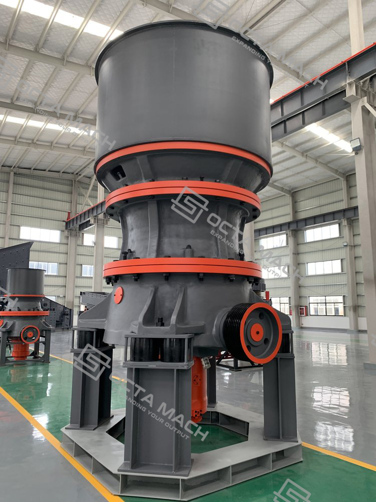
The Single-Cylinder Hydraulic Cone Crusher is a compression crusher used for secondary, tertiary, and fine crushing of hard and abrasive rock after primary size reduction. The motor transfers power through the pulley, horizontal drive shaft, pinion, and large gear to rotate the eccentric sleeve. This eccentric movement causes the moving cone to gyrate around the main shaft, continuously changing the gap between the mantle and concave. Material is compressed when the crushing chamber closes, then moves downward under gravity when the chamber opens.
The main hydraulic cylinder supports hydraulic discharge opening adjustment, overload release, and cavity clearing. Under stable chamber feeding, particles are crushed not only against the liners but also against each other, producing laminating crushing and more controlled product grading. OctaMach supplies CS and CH configurations for granite, basalt, river pebble, iron ore, copper ore, quartzite, and other hard-rock crushing duties.
CS/CH Series Technical Specifications
| Model | Cavity Type | Maximum Inlet Size (mm) | Minimum Outlet Size (mm) | Maximum Installed Power (kW) |
|---|---|---|---|---|
| CS420 | S1 Extra Coarse | 240 | 22 | 90 |
| CS420 | S2 Medium Coarse | 200 | 19 | 90 |
| CH420 | H1 Fine | 135 | 10 | 90 |
| CH420 | H2 Medium Fine | 65 | 8 | 90 |
| CH420 | H3 Extra Fine | 38 | 4 | 90 |
| CS430 | S1 Extra Coarse | 360 | 25 | 160 |
| CS430 | S2 Medium Coarse | 300 | 22 | 160 |
| CS430 | S3 Coarse | 235 | 19 | 160 |
| CH430 | H1 Fine | 185 | 13 | 160 |
| CH430 | H2 Medium Fine | 90 | 10 | 160 |
| CH430 | H3 Extra Fine | 50 | 6 | 160 |
| CS440 | S1 Extra Coarse | 450 | 35 | 250 |
| CS440 | S2 Medium Coarse | 400 | 29 | 250 |
| CS440 | S3 Coarse | 300 | 25 | 250 |
| CH440 | H1 Fine | 215 | 16 | 250 |
| CH440 | H2 Medium Fine | 110 | 13 | 250 |
| CH440 | H3 Extra Fine | 70 | 8 | 250 |
| CS660 | S1 Extra Coarse | 560 | 41 | 315 |
| CS660 | S2 Medium Coarse | 500 | 38 | 315 |
| CH660 | H1 Fine | 275 | 16 | 315 |
| CH660 | H2 Medium Fine | 135 | 16 | 315 |
| CH660 | H3 Extra Fine | 65 | 13 | 315 |
| CH870 | H1 Fine | 300 | 22 | 560 |
| CH870 | H2 Medium Fine | 155 | 19 | 560 |
| CH870 | H3 Extra Fine | 80 | 10 | 560 |
| CH890 | H1 Fine | 370 | 25 | 750 |
| CH890 | H2 Medium Fine | 195 | 22 | 750 |
| CH890 | H3 Extra Fine | 85 | 10 | 750 |
Working Principle, Structure and Hydraulic Control
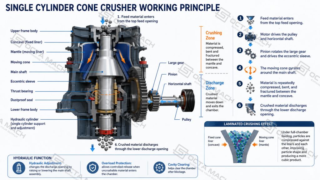
The single cylinder hydraulic cone crusher working principle begins with the horizontal transmission system. The motor drives the pulley and horizontal shaft, the pinion rotates the large gear, and the gear drives the eccentric sleeve. As the eccentric sleeve turns, the moving cone gyrates around the main shaft. Material entering from the top is repeatedly compressed, bent, and fractured between the mantle and concave until it becomes small enough to pass through the lower discharge opening.
The main hydraulic cylinder changes the axial position of the main-shaft and moving-cone assembly. Raising or lowering this assembly changes the discharge opening without manual shim adjustment. When uncrushable material enters the chamber, the hydraulic circuit permits controlled movement of the assembly, enlarging the opening and providing hydraulic overload protection. The system also supports hydraulic tramp release and hydraulic cavity clearing after blockage.
| Main Component | Technical Function | Operating Value |
|---|---|---|
| Upper frame body | Supports the upper crushing chamber | Maintains chamber alignment and structural rigidity |
| Concave | Forms the fixed crushing surface | Determines cavity geometry and feed acceptance |
| Mantle | Forms the moving crushing surface | Transfers compressive force to the material |
| Moving cone | Produces the gyratory crushing action | Creates continuous compression around the chamber |
| Main shaft | Supports the moving-cone assembly | Carries axial and radial crushing loads |
| Eccentric sleeve | Generates eccentric movement | Controls the gyratory path of the moving cone |
| Thrust bearing | Supports axial load | Maintains stable movement under crushing pressure |
| Hydraulic cylinder | Adjusts and supports the moving assembly | Provides setting adjustment, overload release, and clearing |
| Large gear and pinion | Transfer drive torque | Connect the motor to the eccentric assembly |
| Dustproof seal | Restricts dust entry | Protects internal lubrication surfaces |
| Lubricating oil ports | Supply and return oil | Maintain oil flow through the cone crusher lubrication system |
The single-cylinder hydraulic design integrates discharge-opening adjustment, overload protection, and chamber clearing into one hydraulic control system. By raising or lowering the moving-cone assembly, the crusher adjusts the discharge opening without manual shim replacement. When uncrushable material enters the chamber, the hydraulic cylinder permits controlled movement of the assembly, helping protect the main shaft, mantle, concave, and transmission components.
Key advantages include:
- Integrated hydraulic adjustment, overload release, and cavity clearing
- Faster discharge-opening adjustment with less manual intervention
- Multiple cavity profiles for secondary, tertiary, and fine crushing
- Stable compression crushing for hard and abrasive materials
- Inter-particle crushing under uniform chamber feeding
- Independent lubrication and dust-sealing protection for internal components
- Compact structural arrangement with convenient maintenance access
CS and CH Cavity Configurations
The supplied CS models use S-series coarse cavities, while CH models use H-series fine cavities. The cavity must be selected from the actual feed size and crushing duty before the minimum outlet size is finalized.
| Cavity Code | Cavity Description | Feed Condition | Typical Crushing Duty |
|---|---|---|---|
| S1 | Extra Coarse | Larger, well-prepared feed | Coarse secondary crushing |
| S2 | Medium Coarse | Medium-large feed | Secondary crushing |
| S3 | Coarse | Controlled coarse feed | Secondary or intermediate reduction |
| H1 | Fine | Smaller prepared feed | Tertiary crushing |
| H2 | Medium Fine | Controlled fine feed | Tertiary or fine crushing |
| H3 | Extra Fine | Fine and uniform feed | Fine crushing in a matched closed circuit |
The main cone crusher cavity types should be applied according to the following limits:
- S1 and S2 cavities accept larger feed and are matched to secondary cone crusher duties.
- S3 cavities provide further reduction where the feed has already been controlled.
- H1 and H2 cavities are selected for tertiary cone crusher operation with smaller prepared feed.
- H3 cavities require fine, uniform feed and effective upstream screening.
- A coarse cavity should not be operated at an excessively narrow discharge opening to imitate a fine cavity.
- A fine cavity should not receive regular feed above its listed inlet limit.
- Feed opening, minimum outlet size, and screen aperture must be reviewed together.
This separation prevents oversized feed from entering a fine crushing cone crusher configuration and reduces uneven mantle and concave wear.
How to Choose the Right Single-Cylinder Cone Crusher
The correct single-cylinder hydraulic cone crusher should be selected from the complete crushing and screening circuit rather than from installed power, maximum inlet size, or catalogue data alone. Maximum feed size, material hardness, abrasivity, required product grading, crushing stage, and screening arrangement must be reviewed together because each factor affects cavity selection, hydraulic load, liner wear, and actual throughput.
| Selection Factor | Information to Confirm | Effect on Selection |
|---|---|---|
| Maximum feed size | Largest regular lump after primary crushing | Determines model and cavity type |
| Feed gradation | Proportion of coarse particles, intermediate sizes, and fines | Affects chamber filling and actual throughput |
| Required product sizes | Target aggregate or ore fractions | Determines cavity and discharge opening |
| Material hardness | Rock strength and fracture behavior | Influences crushing load and reduction duty |
| Material abrasivity | Quartz, silica, and expected liner wear | Affects maintenance interval and operating cost |
| Crushing stage | Secondary, tertiary, or fine crushing | Defines the required cavity profile |
| Screening circuit | Open or closed circuit | Controls return load and final grading |
| Feed arrangement | Continuous, central, and evenly distributed feed | Supports stable power draw and uniform liner wear |
| Lubrication condition | Oil pressure, temperature, filtration, and flow | Protects the eccentric, gears, bearings, and main shaft |
| Maintenance access | Space for mantle, concave, and internal inspection | Influences the plant layout |
After the preliminary model is identified, the selected cavity and discharge opening should be checked against the upstream jaw crusher, feeder distribution, vibrating-screen aperture, and closed-circuit return load. A larger crusher does not automatically provide more stable production; the best result comes from matching the model, cavity profile, feed condition, lubrication system, and downstream equipment to the same operating duty.
Working Conditions and Applications
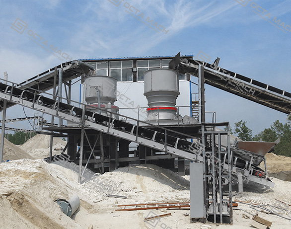
The CS/CH Single-Cylinder Hydraulic Cone Crusher is installed after primary jaw crushing for secondary, tertiary, or fine reduction of hard and abrasive material. The main hydraulic cylinder combines discharge-opening adjustment, overload release, and cavity clearing, while CS and CH cavity configurations match different feed sizes and product requirements.
- Granite and basalt aggregate: CS coarse cavities handle larger prepared feed for secondary crushing; CH fine cavities are used before closed-circuit screening where smaller product sizes are required.
- River pebble crushing: Central, continuous feeding is important because rounded particles can segregate and cause uneven mantle and concave wear.
- Iron and copper ore: Used after coarse crushing to prepare controlled feed for screening or grinding, with cavity selection based on ore hardness and target mill-feed size.
- Quartzite and abrasive rock: Compression crushing is preferred where impact crushing would cause high wear; liner condition and lubrication cleanliness require close control.
- Closed-circuit hard-rock plants: The crusher works with a vibrating screen and return conveyor, so circulating oversize must be included in the total crushing load.
The single-cylinder design performs best with clean, evenly distributed feed within the selected cavity limit. Oversized material, tramp metal, or repeated overload should be corrected upstream rather than handled continuously by the hydraulic protection system.
Why Choose OctaMach
OctaMach selects the crusher from the actual material, maximum feed size, cavity requirement, final product, and complete process layout. As a single cylinder hydraulic cone crusher manufacturer, OctaMach supports both the crusher and the connected feeding, screening, and conveying equipment.
FAQ
Q1:How should the cavity type of a single-cylinder hydraulic cone crusher be selected?
A1:Select the cavity from the largest regular feed size and crushing stage first, then confirm the discharge opening and screen aperture. A fine cavity should not receive oversized feed, while a coarse cavity should not be forced to produce fine material through an excessively small opening.
Q2:Why is the actual capacity lower than the catalogue capacity?
A2:Actual capacity falls when feed is segregated, contains excessive fines or moisture, or exceeds the selected cavity limit. Worn liners, uneven feeding, a narrow discharge opening, and high closed-circuit return load also increase the crusher’s internal duty.
Q3:How does hydraulic overload protection work in a single-cylinder cone crusher?
A3:When uncrushable material creates abnormal chamber pressure, the hydraulic system allows controlled movement of the main-shaft and moving-cone assembly to enlarge the discharge opening. After the obstruction passes, hydraulic pressure returns the assembly to its operating position.
Q4:When should a single-cylinder cone crusher be selected instead of a multi-cylinder model?
A4:Select the design from feed size, cavity requirement, crushing stage, maintenance access, and control method—not cylinder count alone. A single-cylinder crusher integrates setting adjustment, overload release, and cavity clearing through one main hydraulic system, while a multi-cylinder design uses a different locking and protection arrangement.